Measuring acceleration using interferometry with reduced environmental effects
Inactive Publication Date: 2017-07-27
BAKER HUGHES INC
View PDF2 Cites 1 Cited by
Summary
Abstract
Description
Claims
Application Information
AI Technical Summary
This helps you quickly interpret patents by identifying the three key elements:
Problems solved by technology
Method used
Benefits of technology
Benefits of technology
The patent describes an apparatus and method for measuring acceleration using a reference cavity and a sense cavity. The apparatus includes a laserlight source, a photodetector, and an interferometer sensor. The method involves illuminating the cavities with light, detecting the light emitted, and measuring the displacement of the reflecting surfaces in each cavity. The acceleration is then calculated using the displacement measurements. The technical effects of the patent include improved accuracy and sensitivity in measuring acceleration and the ability to measure acceleration in a downhole environment.
Problems solved by technology
One challenge faced by instruments disposed deep within the earth is high temperature, which can meet or exceed 200° C. The high temperature can cause an accelerometer to fail or provide inaccurate measurements.
Method used
Image
Click on the blue label to locate the original text in one second.
Reading with bidirectional positioning of images and text.
Examples
first embodiment
where the “hat” represents calibration data and the average is taken over the entire set. During operation of the sensor, the laser is locked to both fixed wavelength points and its driving parameters measured, (I0,1(t), T0,1(t)) and (I0,2(t), T0,2(t)) similar to the first embodiment described beginning in paragraph [0034]. These points are used to adjust the point about which Taylor expansion was used keeping the coefficients fixed and the ratios
are used to scale the coefficients of the Taylor expansion. (See FIG. 8B).
second embodiment
[0039]In another embodiment, the laser is locked to three or more fixed wavelength reference points, λ0,N. During calibration, similar to the first and the tuning parameters are changed keeping the wavelength fixed at each reference point. This improves the accuracy and dynamic range of the fitted Taylor expansion. (See FIG. 8C).
[0040]During sensor operation, single measurements at each of the fixed wavelengths are made periodically and the linear terms in the Taylor expansion are calculated “on the fly.” The ratio of the linear terms estimated during calibration to the linear terms estimated during sensor operation are used to adjust the higher order terms, if any, in the Taylor expansion.
[0041]In a fourth method, two or more laser sources are used to increase 4X, the dynamic range of the wavelength source. This method of wavelength variation is similar to the second / third method, with the addition of more than one overlapping gain-spectrum laser source. The gain spectra of each l...
embodiment 1
[0085] An apparatus for measuring acceleration, the apparatus comprising: a reference cavity comprising an optical medium and a first fixed reflecting surface and a second fixed reflecting surface disposed a distance dREF from the first fixed reflecting surface; a sense cavity comprising the optical medium and a fixed reflecting surface and a non-fixed reflecting surface disposed a distance dSENSE from the fixed reflecting surface, the non-fixed reflecting surface being configured to be displaced when subject to an acceleration force; a light source configured to illuminate the reference cavity and the sense cavity; a controller configured to vary a wavelength of light emitted by the light source and / or an index of refraction of the optical medium; a photodetector configured to detect light emitted by the reference cavity and the sense cavity; an interferometer sensor configured to measure using the light detected by the photodetector, for each variation of the wavelength of light e...
PUM
Abstract
An apparatus for measuring acceleration includes: a reference cavity having a first fixed reflecting surface and a second fixed reflecting surface; a sense cavity having a fixed reflecting surface and a non-fixed reflecting surface, the non-fixed reflecting surface being configured to be displaced when subject to an acceleration force; a light source to illuminate the reference and sense cavities; a controller to vary a wavelength of light emitted by the light source and / or an index of refraction of an optical medium of the cavities; a photodetector to detect light emitted by the reference and sense cavities; an interferometer sensor to measure using the detected light, for each variation of the wavelength of light and / or the index of refraction a reference displacement of the reference cavity and a sense displacement of the sense cavity; and a processor to calculate the acceleration using each of the reference displacements and the sense displacements.
Description
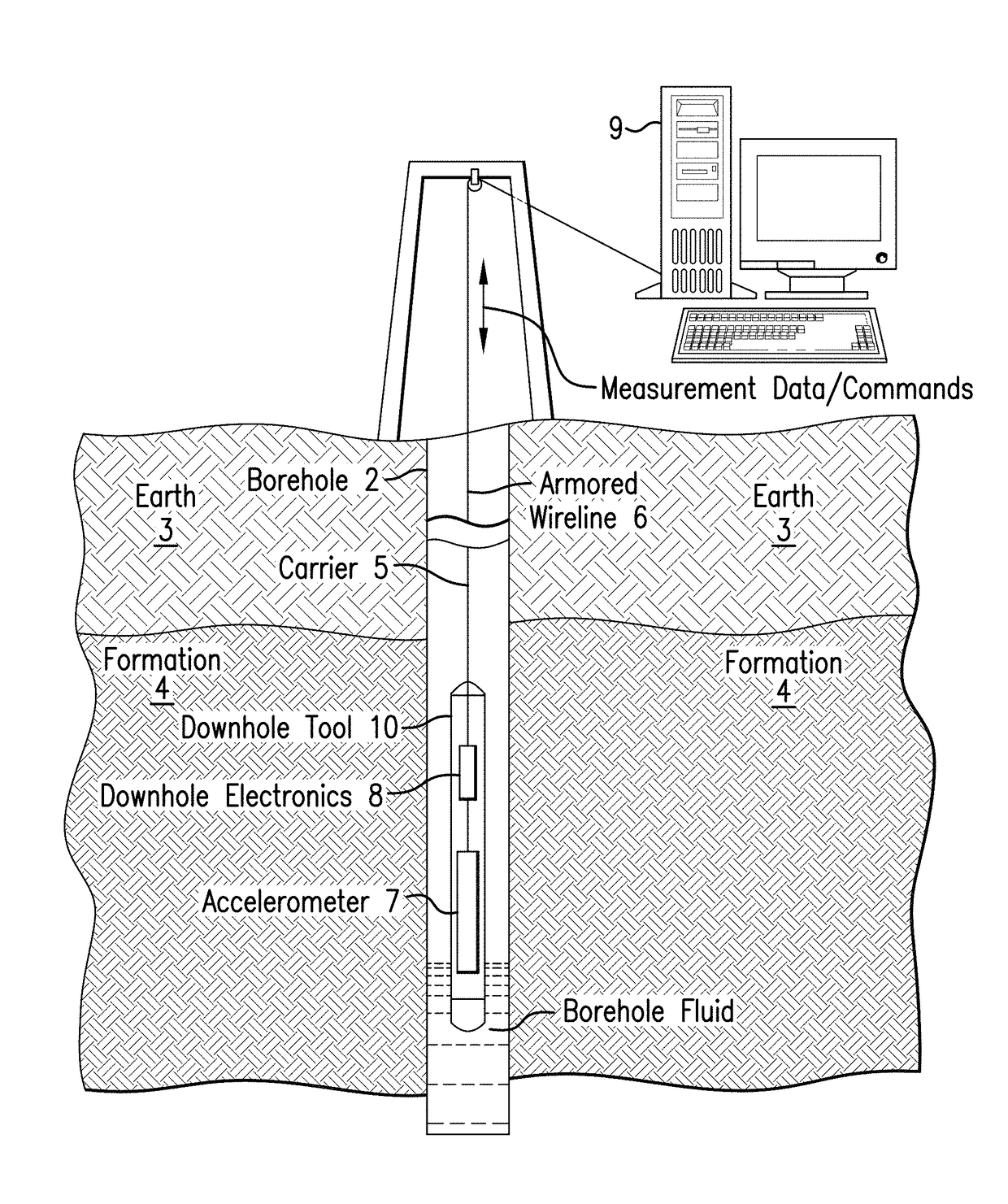
BACKGROUND[0001]There are many applications for accelerometers used beneath the surface of the earth. In one application, accelerometers are attached to a drill string having a drill bit for drilling a borehole into the earth. The accelerometers can measure vibrations that may cause equipment damage or slow down the rate of penetration and thus be used adjust drilling parameters to reduce vibrations.[0002]In another subsurface application, an accelerometer with increased sensitivity may be used as a gravimeter to measure gravitational force and thus gravitational acceleration. By sensing gravitational acceleration below the surface of the earth, various properties of a reservoir can be sensed for reservoir management purposes.[0003]One challenge faced by instruments disposed deep within the earth is high temperature, which can meet or exceed 200° C. The high temperature can cause an accelerometer to fail or provide inaccurate measurements. Hence, improvements to accelerometers for s...
Claims
Application Information
Patent Timeline
Application Date:The date an application was filed.
Publication Date:The date a patent or application was officially published.
First Publication Date:The earliest publication date of a patent with the same application number.
Issue Date:Publication date of the patent grant document.
PCT Entry Date:The Entry date of PCT National Phase.
Estimated Expiry Date:The statutory expiry date of a patent right according to the Patent Law, and it is the longest term of protection that the patent right can achieve without the termination of the patent right due to other reasons(Term extension factor has been taken into account ).
Invalid Date:Actual expiry date is based on effective date or publication date of legal transaction data of invalid patent.

