

Integrated antenna device
- Summary
- Abstract
- Description
- Claims
- Application Information
AI Technical Summary
Benefits of technology
Problems solved by technology
Method used
Image

Examples
Embodiment Construction
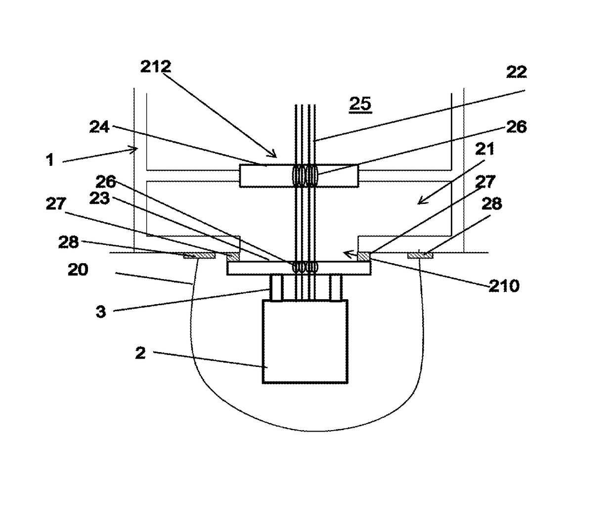
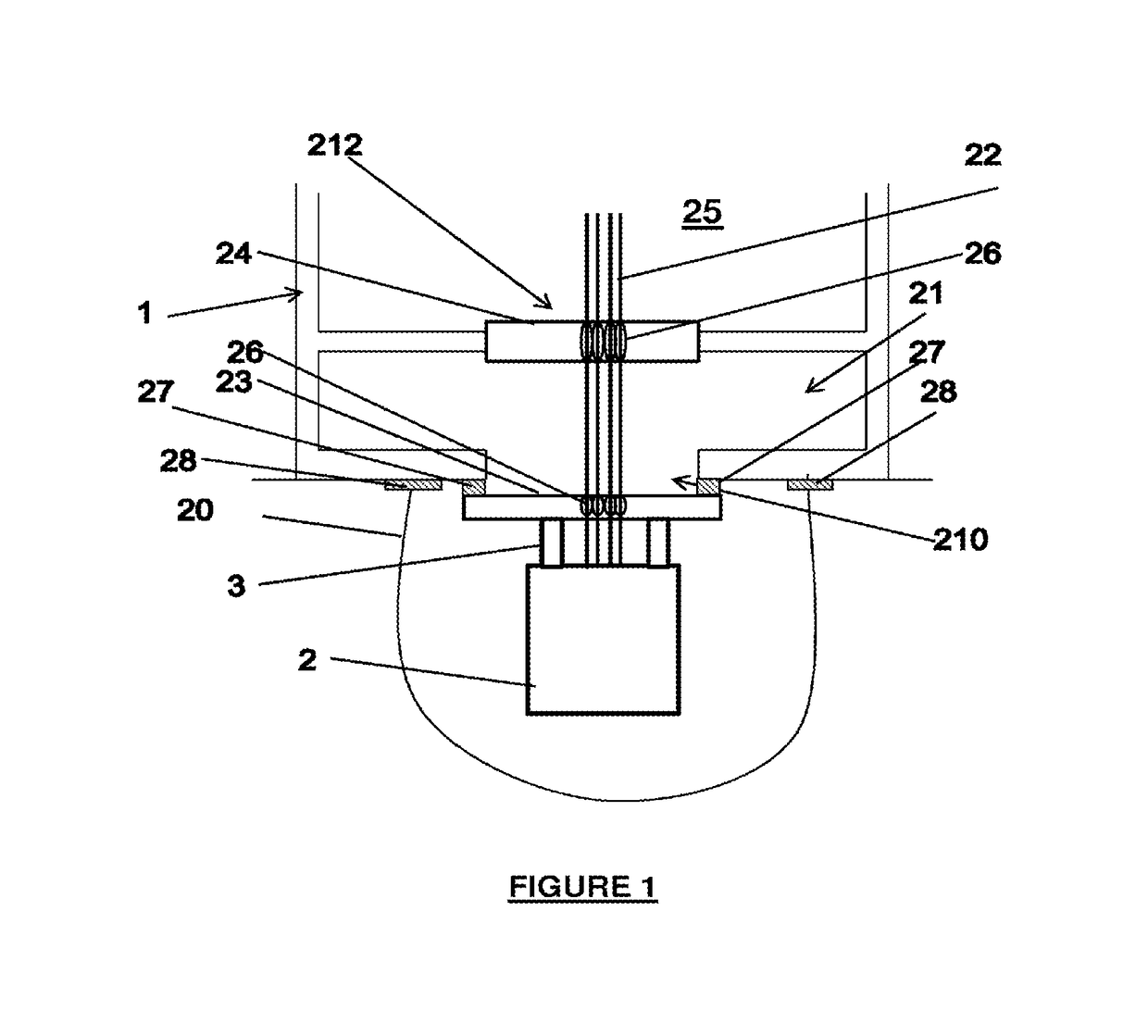
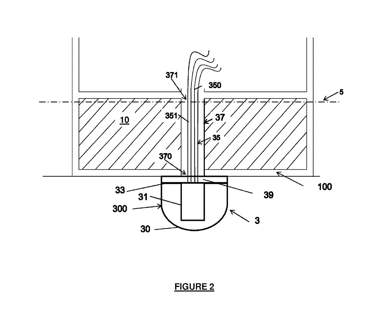
[0044]FIG. 2 is a diagram representing an exemplary structure 10 on which an integrated antenna device 3 can be mounted, according to certain embodiments.
[0045]The integrated antenna device 3 can be mounted on any fixed or mobile structure 10, intended to be immersed at least partially in the water (for example at sea), such as for example a floating or anchored marine platform or a surface vessel. The structure 10 can in particular comprise a platform emerged above the water level 5 (also called the “water line” hereinafter).
[0046]The integrated antenna device 3 comprises a protective casing 300 of hydrodynamic shape delimiting an inner cavity and an antenna 31 arranged inside the inner cavity delimited by the casing 300.
[0047]The antenna can consist of an assembly of transducers, for example stacked, configured to ensure the reception and / or emission of signals. The base of the antenna can in particular be fixed to the casing 300, on its upper wall. It should be noted that such fi...
PUM
 Abstract
Description
Claims
Application Information