Calibration of gyroscopic systems with vibratory gyroscopes

Active Publication Date: 2014-08-12
SAFRAN ELECTRONICS & DEFENSE
View PDF8 Cites 1 Cited by
  • Summary
  • Abstract
  • Description
  • Claims
  • Application Information

AI Technical Summary

Benefits of technology

[0014]The present invention

Problems solved by technology

However, this type of gyroscope is expensive.
Moreover, such a gyroscope used in whole angle mode has a bias error the value of which depends on the vibration position with respect to the case.
The measurement values provided by such a vibratory gyroscope can therefore be impaired by certain errors that relate to the changes in the bias, since the bias value depends on the vibration position and therefore on the changes in the attitude of the carrier.
On the other

Method used


Image

  • Calibration of gyroscopic systems with vibratory gyroscopes
  • Calibration of gyroscopic systems with vibratory gyroscopes

Examples


Example

[0059]Hereafter, the present invention is described in its application to Type I gyroscopes. These Type I gyroscopes correspond to the axisymmetric gyroscopes of the Coriolis Vibratory Gyroscopes (CVG) type, such as for example of the Hemispherical Resonator Gyroscope (HRG) type, as described in the document ‘Type I and Type II micromachined vibratory gyroscopes’ by Andrei M. Shkel, pages 586-593, IEEE / ION (Institute of Electrical and Electronics Engineers / Institute Of Navigation' PLANS 2006, San Diego, Calif., USA).

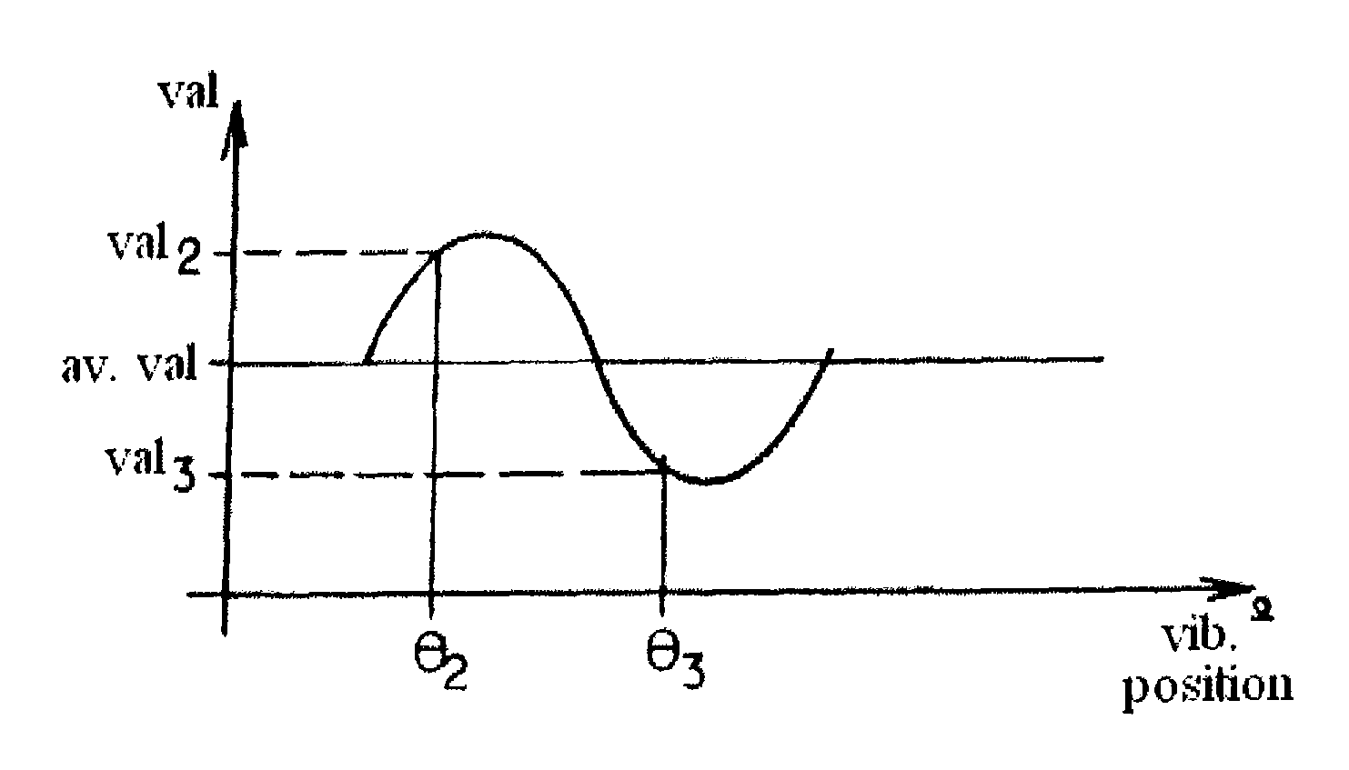
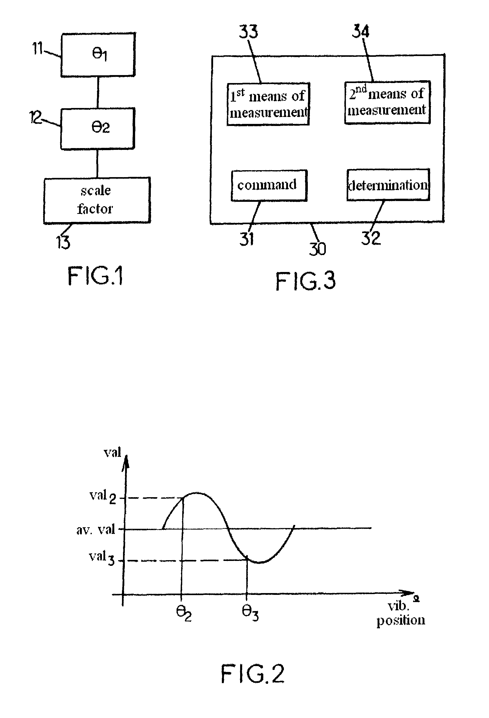
[0060]These gyroscopes can operate in an open loop, i.e. in whole angle mode. They then make it possible to measure an absolute rotation angle on the basis of a measurement of an angle representing the vibration position of the gyroscope with respect to measurement electrodes.

[0061]Such a gyroscope can also be used in a closed loop by the control of the vibration position via an electrical command, the so-called precession command, as described in particular in document ...


PUM


Abstract

In a gyroscopic system comprising at least four vibratory gyroscopes, a first measurement is provided by said vibratory gyroscope to be calibrated, and a second measurement is provided by a combination of the measurements from the other vibratory gyroscopes of the system. At the level of the vibratory gyroscope to be calibrated, an initial command is applied in order to command a change in position from a first vibration position (θ1) to a second vibration position (θ2). A calibrated scale factor value of the vibratory gyroscope to be calibrated is then determined on the basis of a calculated value in relation to the change in position, based on the period of time during which the initial command is applied, the initial command, an angular difference between the first and second vibration positions measured according to the first measurement and an angular difference between the first and second vibration positions measured according to the second measurement.

Description

CROSS-REFERENCE TO RELATED APPLICATIONS[0001]This application is a U.S. national stage filing under 35 USC §371 of International Patent Application No. PCT / EP2009 / 066001 filed on Nov. 27, 2009, which claims priority under the Paris Convention to the French Patent Application No. 08 58145, filed on Nov. 28, 2008.FIELD OF THE DISCLOSURE[0002]The present invention relates to gyroscopic systems, such as in particular inertial navigation units, and more particularly to gyroscopic systems that are based on the use of vibratory gyroscopes.BACKGROUND OF THE DISCLOSURE[0003]An inertial unit is a precision navigation device that comprises in particular gyroscopes in order to be able to provide navigation information for carriers such as ships, aircraft, missiles or all types of space vehicle.[0004]The level of precision required for the measurements provided by the gyroscopes used in these inertial units depends on the type of inertial unit considered. Certain units, such as strapdown inertia...

Claims


Application Information

Patent Timeline
IPC IPC(8): G12B13/00G01C19/56
CPCG01C19/56G01C25/005
Inventor CARON, JEAN-MICHEL
Owner SAFRAN ELECTRONICS & DEFENSE
Why Eureka
Try Eureka