

Differentiated viewing device provided with active spectacles
- Summary
- Abstract
- Description
- Claims
- Application Information
AI Technical Summary
Benefits of technology
Problems solved by technology
Method used
Image

Examples
first embodiment
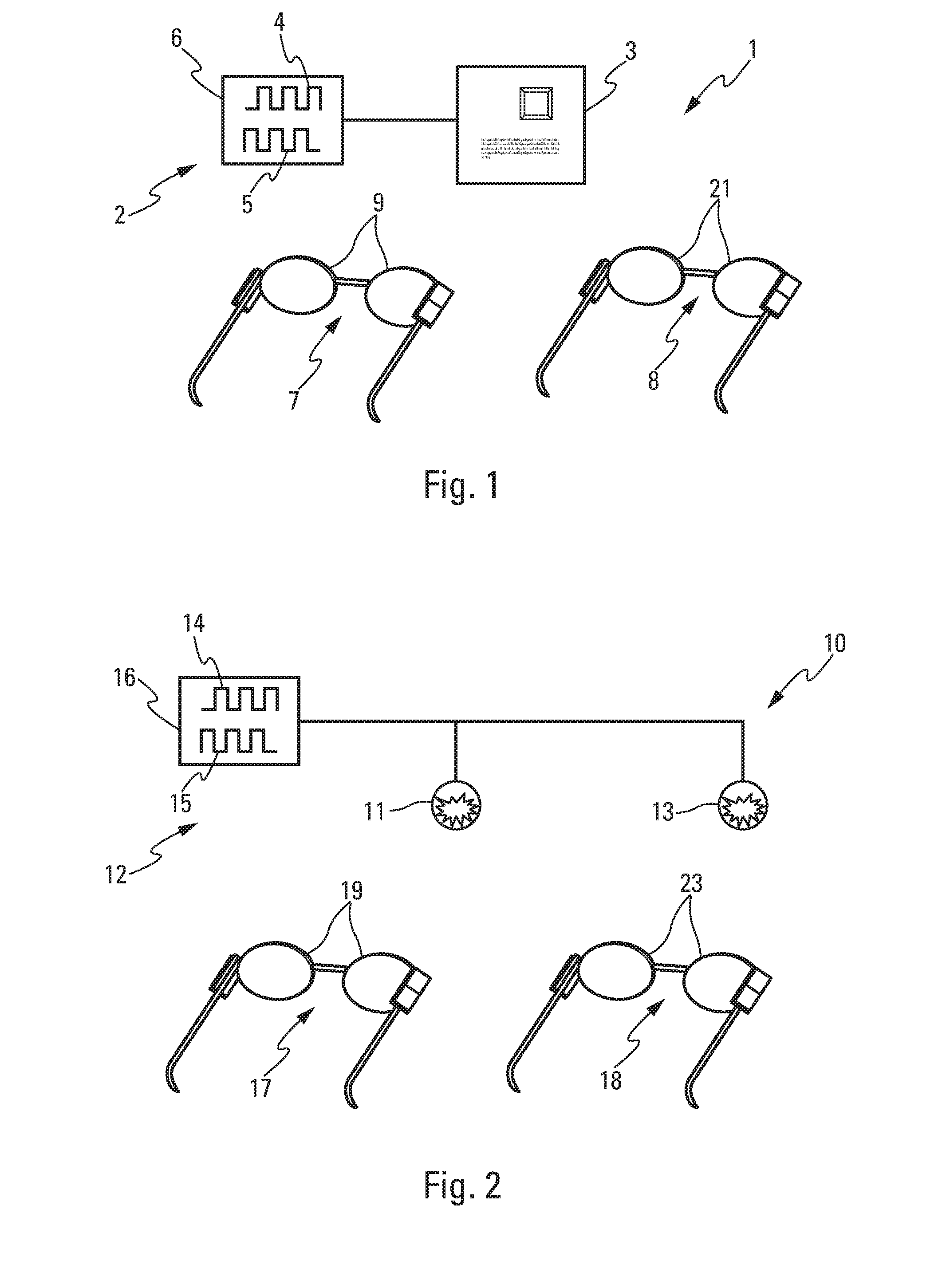
[0051]FIG. 1 shows a differentiated viewing device 1, notably for a motor vehicle. The device 1 comprises a light system 2 provided with a data display 3, for example a liquid crystal display of LCD type. The display 3 is, for example, arranged on the dashboard of the vehicle, not represented in the figures, between the place for the driver and that for the passenger so as to be able to be seen by two people seated in the places. In a variant embodiment, the light system 2 is a head-up display, of HUD type.
[0052]The display 3 is configured to selectively emit first and second light signals 4, 5. In other words, the display 3 successively presents first light signals 4, which are for example navigation data or vehicle status data, and second light signals 5, which are for example linked to the display of an entertainment video. The first light signals 4 are intended for the driver of the vehicle, and the second signals 5 are intended to be seen by a passenger of the vehicle.
[0053]For...
second embodiment
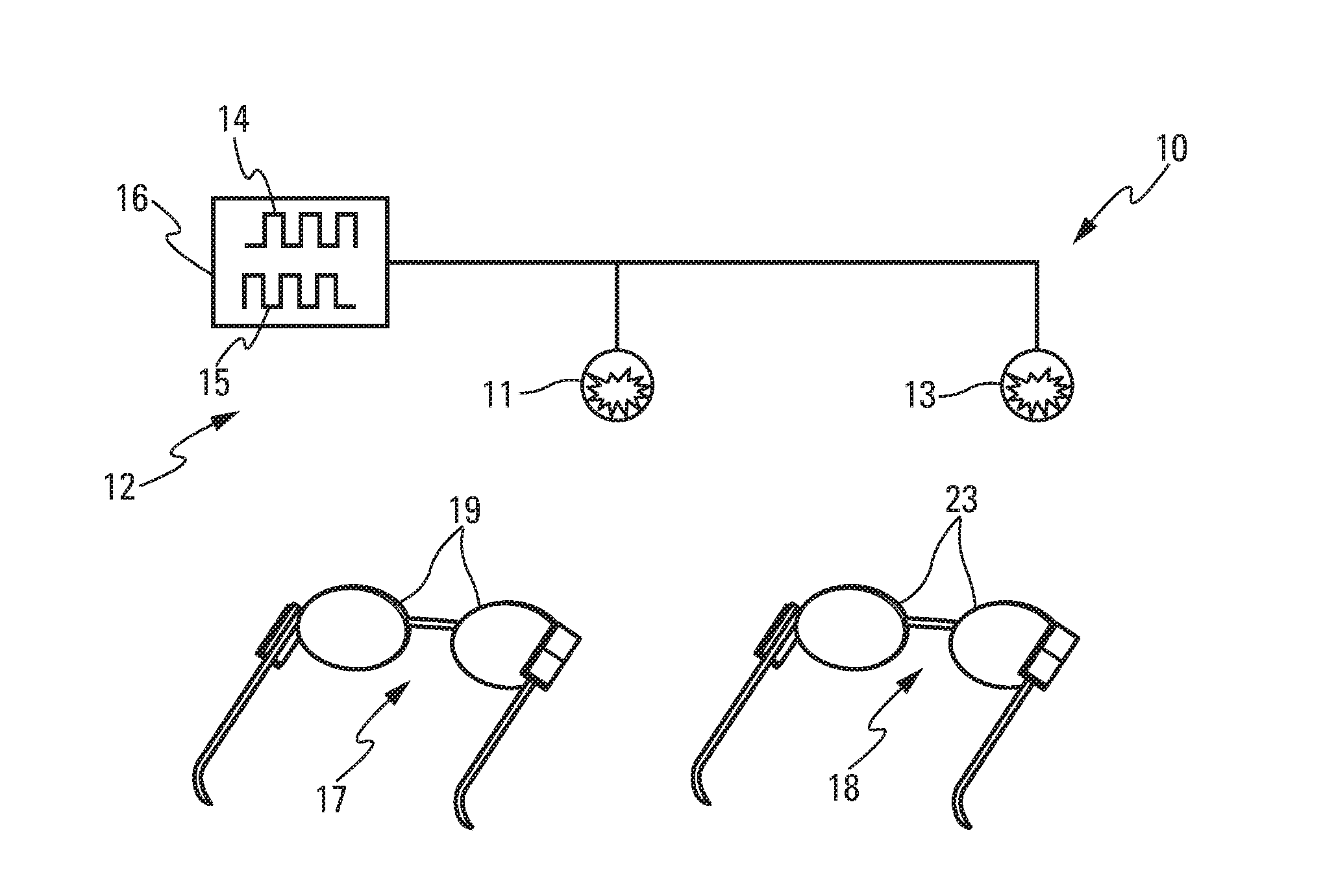
[0065]In a second embodiment, represented in FIG. 2, the differentiated viewing device 10 comprises a lighting device as light system 12, notably of a motor vehicle interior. The light system 12 here comprises two lighting means, for example two lamps 11, 13 of different intensity or color. The first light signals 14 are here emitted by a first lamp 11 and the second light signals 15 by a second lamp 13. The lamps 11, 13 are controlled by a control unit 16.
[0066]This lighting device or system 12 is used here to light up the interior differently for the driver and the passenger, without one perceiving the lighting intended for the other. As in the first embodiment, the first lamp 11 is synchronized at a modulation frequency with a first pair of spectacles 17 provided with a first screen 19, and the second lamp 13 is synchronized, at the same modulation frequency, with the second pair of spectacles 18 provided with a second screen 23. The first and second pairs of spectacles 17, 18 op...
PUM
 Abstract
Description
Claims
Application Information