
Umbrella
a technology of umbrellas and hoop straps, applied in the field of umbrellas, can solve problems such as turning the umbrella inside out, and achieve the effects of reducing the combined length of each canopy tensioner, reducing the hoop stress in the canopy, and reducing the hoop stress
- Summary
- Abstract
- Description
- Claims
- Application Information
AI Technical Summary
Benefits of technology
Problems solved by technology
Method used
Image

Examples
Embodiment Construction
[0054]In the following detailed description, reference is made to accompanying drawings which form a part of the detailed description. The illustrative embodiments described in the detailed description, depicted in the drawings and defined in the claims, are not intended to be limiting. Other embodiments may be utilised and other changes may be made without departing from the spirit or scope of the subject matter presented. It will be readily understood that the aspects of the present disclosure, as generally described herein and illustrated in the drawings can be arranged, substituted, combined, separated and designed in a wide variety of different configurations, all of which are contemplated in this disclosure.
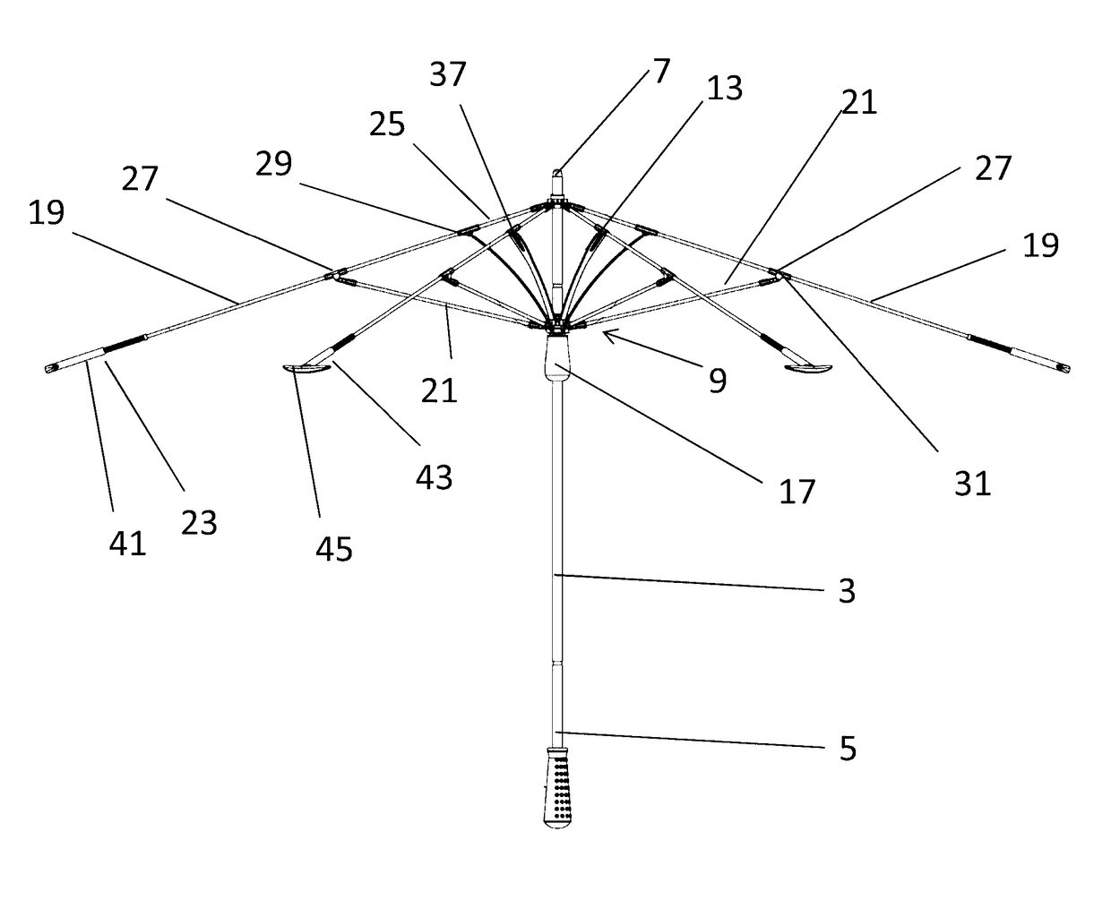
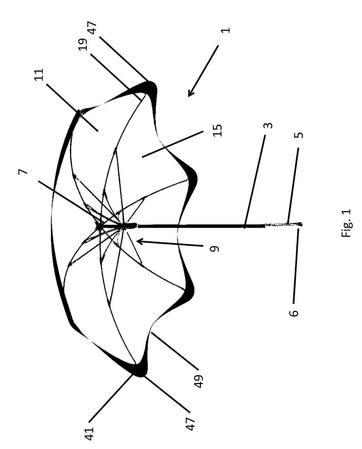
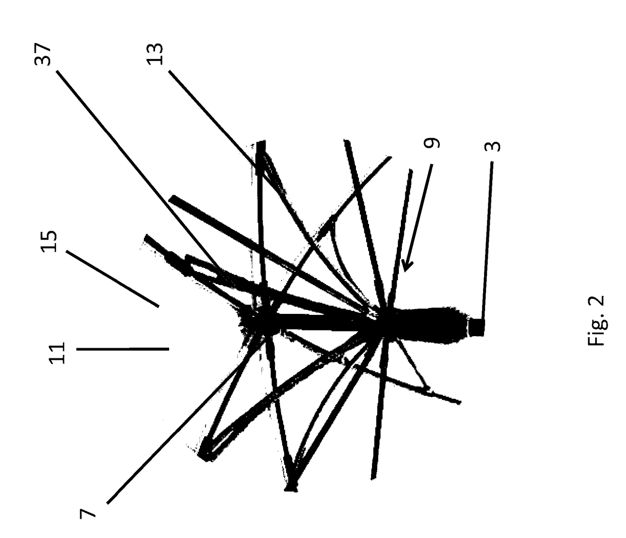
[0055]Referring firstly to FIG. 1, an umbrella 1 according to the present disclosure is described. The umbrella 1 includes an elongate member, in the form of shaft 3, having proximal 5 and distal end 7 portions. The shaft 3 includes a handle 6 at its proximal end 5 that all...
PUM
 Abstract
Description
Claims
Application Information