Umbrella

a technology of umbrellas and hoop straps, applied in the field of umbrellas, can solve problems such as turning the umbrella inside out, and achieve the effects of reducing the combined length of each canopy tensioner, reducing the hoop stress in the canopy, and reducing the hoop stress

Active Publication Date: 2019-11-05
BRAND DEVERS
View PDF16 Cites 2 Cited by
  • Summary
  • Abstract
  • Description
  • Claims
  • Application Information

AI Technical Summary

Benefits of technology

[0008]In some forms, when the umbrella is in an inverted position, each biasing means may be able to move towards its neutral position (i.e. by tending to straighten) upon release of the applied force such that the support structure is biased towards the erect position. This enables the umbrella to be self-righting.
[0021]In some forms, each canopy tensioner may further comprise a resilient member that, in use, can be disposed about the first end of a respective arm. The resilient member may be constrained from movement along the arm by the body and a locator that is mounted to the arm. The locator may be spaced from the first end of the arm. This allows for the tension in the canopy and support structure to be limited in the event that the canopy inverts.
[0037]In some forms, the canopy tensioner may be configured to reduce the hoop stress in the canopy when the support structure is adjusted between the erect position and an inverted position. In some forms, each alignment member may be configured to displace laterally with respect to its respective elongate member upon adjustment of the support structure between the erect position and the inverted position to thereby decrease a combined length of each canopy tensioner and its respective elongate member to thereby reduce the hoop stress in the canopy.
[0038]Also disclosed herein is an umbrella that comprises an elongate member having proximal and distal end portions. A support structure that is connectable to a canopy may be disposed about the distal end portion of the elongate member. The support structure may be adjustable between an erect position, whereby the canopy is able to be tensioned by the support structure, and a collapsed position. The tension in the canopy may be able to be released. The umbrella may also comprise a plurality of biasing means mounted to both the support structure and the distal end portion of the elongate member. Each biasing means may be configured to bias the support structure towards, so as to return the support structure to, the erect position when the umbrella is inverted. Advantageously, this allows for the umbrella to be self-righting, in that the umbrella can return itself to the erect position in the event that that canopy and support structure are inverted (e.g. the umbrella is folded inside out).

Problems solved by technology

A problem with umbrellas is that they catch the wind and the force exerted by the wind on the underside of the canopy can turn the umbrella inside out (e.g. invert the collapsible canopy structure).

Method used


Image

  • Umbrella
  • Umbrella
  • Umbrella

Examples


Embodiment Construction

[0056]In the following detailed description, reference is made to accompanying drawings which form a part of the detailed description. The illustrative embodiments described in the detailed description, depicted in the drawings and defined in the claims, are not intended to be limiting. Other embodiments may be utilised and other changes may be made without departing from the spirit or scope of the subject matter presented. It will be readily understood that the aspects of the present disclosure, as generally described herein and illustrated in the drawings can be arranged, substituted, combined, separated and designed in a wide variety of different configurations, all of which are contemplated in this disclosure.

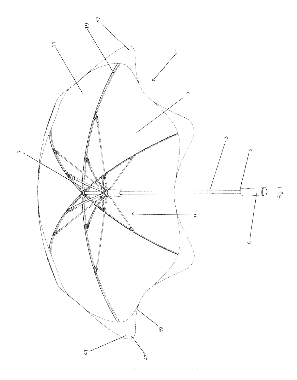
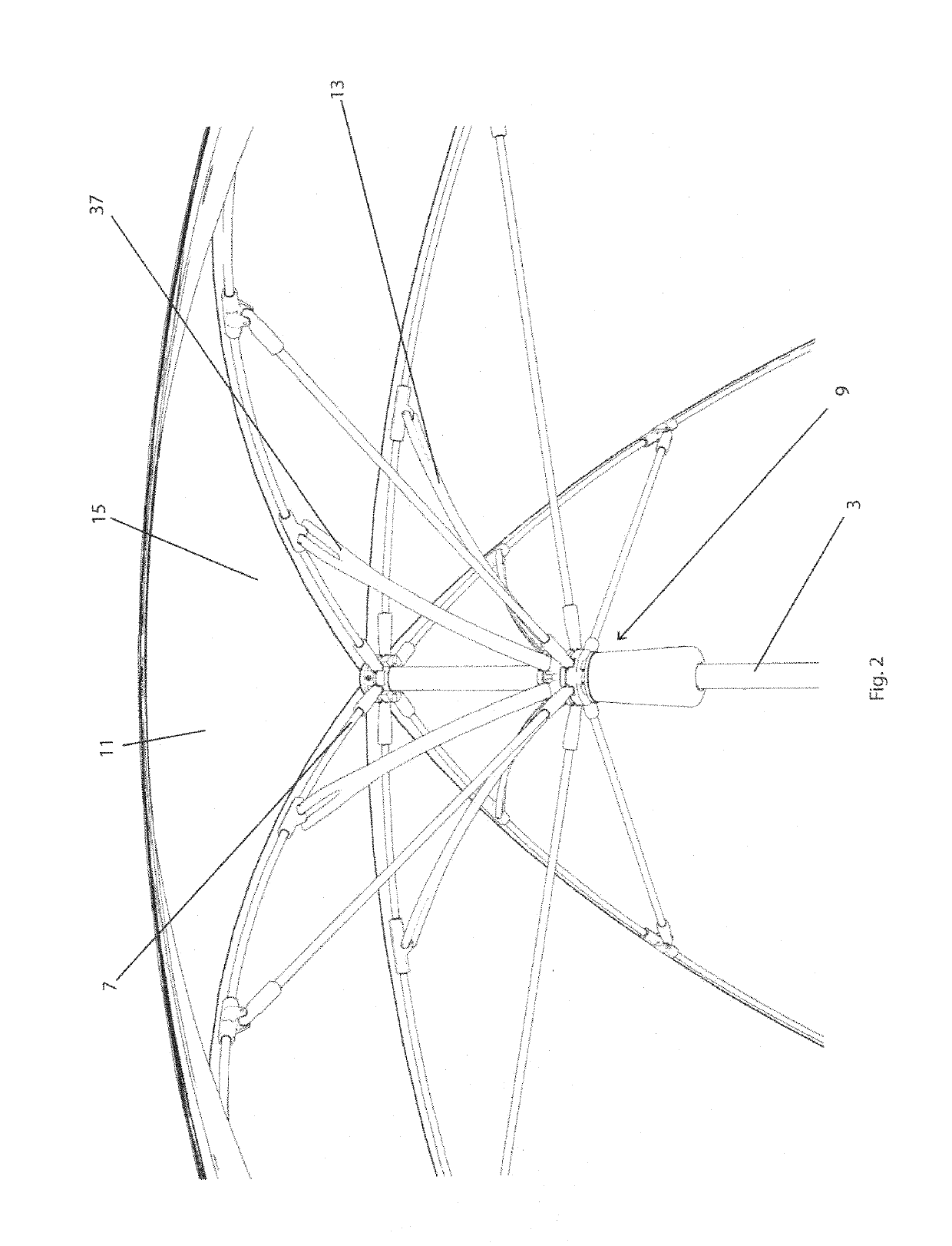
[0057]Referring firstly to FIG. 1, an umbrella 1 according to the present disclosure is described. The umbrella 1 includes an elongate member, in the form of shaft 3, having proximal 5 and distal end 7 portions. The shaft 3 includes a handle 6 at its proximal end 5 that all...


PUM


Abstract

Disclosed is an umbrella that can be used as a canopy to protect a user against rain or sunlight. The umbrella may comprise an elongate member having proximal and distal end portions, a support structure that is connectable to a canopy able to be disposed about the distal end portion of the elongate member, the support structure being be adjustable between an erect position, whereby the canopy is able to be tensioned by the support structure, and a collapsed position, whereby the tension in the canopy is able to be released. The umbrella may also include a plurality of biasing means configured to inhibit the support structure from inverting.

Description

RELATED APPLICATIONS[0001]This application is filed under 35 U.S.C. § 371 as the U.S. national phase of International Patent Application No. PCT / AU2015 / 000576, filed Sep. 18, 2015, which designated the U.S. and claims priority to Australian Patent Application No. 2014903753, filed Sep. 19, 2014. The entire disclosure of both applications, including any drawings, is hereby incorporated herein by reference.TECHNICAL FIELD[0002]This disclosure relates to umbrellas that can be used as a canopy to protect a user against rain or sunlight.BACKGROUND OF THE INVENTION[0003]Umbrellas, or parasols, can be used as a canopy to protect a user from the sun, wind or rain. Umbrellas may be portable structures or may be fixed to the ground. Umbrellas may include a shaft that has a handle at one end and a canopy at the other end. A collapsible canopy support structure may be included to support the canopy and, when not in use, allows for the canopy to collapsed. The collapsible canopy support structur...

Claims


Application Information

Patent Timeline
Patent Type & Authority Patents(United States)
IPC IPC(8): A45B25/22A45B25/06A45B25/08A45B25/16A45B25/02
CPCA45B25/08A45B25/02A45B25/16A45B25/06A45B25/22
Inventor HALTON, PHILIPPATAIT, BRENDON
Owner BRAND DEVERS
Why Eureka
Try Eureka