Process for producing roll of microporous plastic film

a microporous plastic and film production technology, applied in the direction of cell components, cell component details, transportation and packaging, etc., can solve the problems of affecting the production efficiency of the film, the difficulty of aforementioned methods alone to convey the film without causing either wrinkle or breakage, and the difficulty of preventing wrinkles and breakage. , to achieve the effect of preventing breakage and wrinkles, accelerating the stress concentration in the cut portions, and preventing wrinkles

Inactive Publication Date: 2014-01-16
TORAY IND INC
View PDF3 Cites 20 Cited by
  • Summary
  • Abstract
  • Description
  • Claims
  • Application Information

AI Technical Summary

Benefits of technology

[0089]An appropriately selected tension may be used to realize the effect of the invention, but from the viewpoint of breakage prevention, it is preferable to use a smaller tension as compared to cases with general resin films. For instance, it is preferably in the range of 1 N / m to 30 N / m.
[0090]The tension is more preferably in the range of 5 N / m to 20 N / m to allow breakage and wrinkle to be prevented easily while controlling the tension in the machine with appropriate accuracy.
[0091]Here, breakage caused between conveyance rollers 2 is mainly attributed to a slight difference in speed taking place between the conveyance rollers. This is because there is a non-zero speed control error when a plurality of motors are involved in driving the rollers, and in the case of the example shown in FIG. 1, a difference in speed can take place as a result of slippage between a pulley and a drive controller 4 working to drive the conveyance rollers 2 as well as an error in the outside diameters of pulleys. In these cases, the difference in speed causes stress concentration around micropores existing in the microporous plastic film, easily leading to its breakage.
[0092]The mechanism of breakage caused by a difference in speed is as follows. In the case where no slippage takes place, the strain ∈ caused in the microporous plastic film 1 pulled by the difference in speed in FIG. 1 is considered to be roughly expressed by formula 3, where V2 is the circumferential rotation speed of the conveyance roller 21 and V1 is the circumferential rotation speed of the conveyance roller 23 assuming V2>V1. According to Hooke's law, the stress σ1 caused by this strain is expressed by formula 4, where E represents Young's modulus of the microporous plastic film 1 in the length direction.[formula3]ɛ≅V2-V1V1(formula3)[formula4]σ1=Eɛ≅EV2-V1V2(formula4)
[0093]On the other hand, the stress σ2 caused by rotating core torque is expressed by formula 5, where T represents the tension applied during the process to a unit width of the microporous plastic film 1 and t represents the thickness of the microporous plastic film 1.[formula 5]σ2=Tt  (formula 5)
[0094]Breakage occurs when the inequality of formula 6 is met, where σb represents the rupture stress of the microporous plastic film 1. Here, σb can be determined from rupture test of the microporous plastic film 1 using a tensile tester or the like. In the case of a micropore-containing film, however, scratches tend to be caused by the blades of a continuous cutting device installed in the production process to accelerate the stress concentration in the cut portions. Consequently, breakage tends to occur at a stress that is smaller than the rupture stress obtained from the aforementioned tensile test. The inventors of the present invention found that breakage can be prevented by minimizing the value of σ1. Thus, the strain ∈ is prevented from being caused by a difference in speed and the stress is maintained below σb by decreasing the coefficient of static friction between the film and that portion of a conveyance roller 2 which comes in contact with the film. This successfully worked to prevent breakage.[formula 6]σb<σ1+σ2  (formula 6)EXAMPLES

Problems solved by technology

For conventional processes in which a microporous plastic film for separators of secondary batteries and the like is conveyed and wound up into a roll, it has been very difficult to prevent wrinkle and breakage attributable to micropores.
According to knowledge of the present inventors, however, it is difficult to freely adjust the tension of a film that is low in resistance to breakage and liable to deformation in the thickness direction, such as microporous plastic film.
Accordingly, it has been difficult for the aforementioned method alone to convey a film without causing either wrinkle or breakage.
According to knowledge of the present inventors, however, the surface smoothness of microporous plastic film is not a factor in the increase in the friction coefficient, and therefore, it is difficult to prevent wrinkle by adding particles by the method proposed in patent document 1.
Furthermore, particles cannot serve at all for solving the problem of breakage.
However, the objective of this reference is to clarify the mechanism of friction and also clarify the substantial friction phenomenon under air lubrication, and it shows no specific methods to prevent both wrinkle and breakage of microporous plastic films.
Although some studies have insisted that the reduction in friction coefficient is effective for the decrease of wrinkles attributable to conveyance, but according to knowledge of the present inventors, microporous plastic films require special solution to problems with their unique friction generation mechanism, and non-patent document 3 is not successful in showing a specific method to prevent both wrinkle and breakage.
According to knowledge of the present inventors, however, friction coefficient reduction effect of a DLC layer is developed by preventing minute deformation and reducing the real contact area of the surface by virtue of high hardness of the DLC layer, and therefore, it cannot be highly effective for the phenomenon in which the friction coefficient increases by virtue of the flexibility of microporous plastic film itself.
According to knowledge of the present inventors, however, although it can be expected in the case of synthetic resin films with a smooth surface dealt with in patent document 3 that the friction coefficient can be reduced by decreasing protrusions on, that is, decreasing the roughness of, the roller surface and by making use of a phenomenon that is considered to be air lubrication, such air lubrication cannot be expected in the case of a microporous plastic film, which will undergo air release through micropores, and its contact with a smooth metal surface will increase the friction coefficient contrary to expectation, thus failing to prevent wrinkle and breakage.
As stated above, no techniques have been available conventionally to convey a microporous plastic film and wind it up into a roll without wrinkle or breakage.

Method used


Image

  • Process for producing roll of microporous plastic film
  • Process for producing roll of microporous plastic film
  • Process for producing roll of microporous plastic film

Examples


example 1

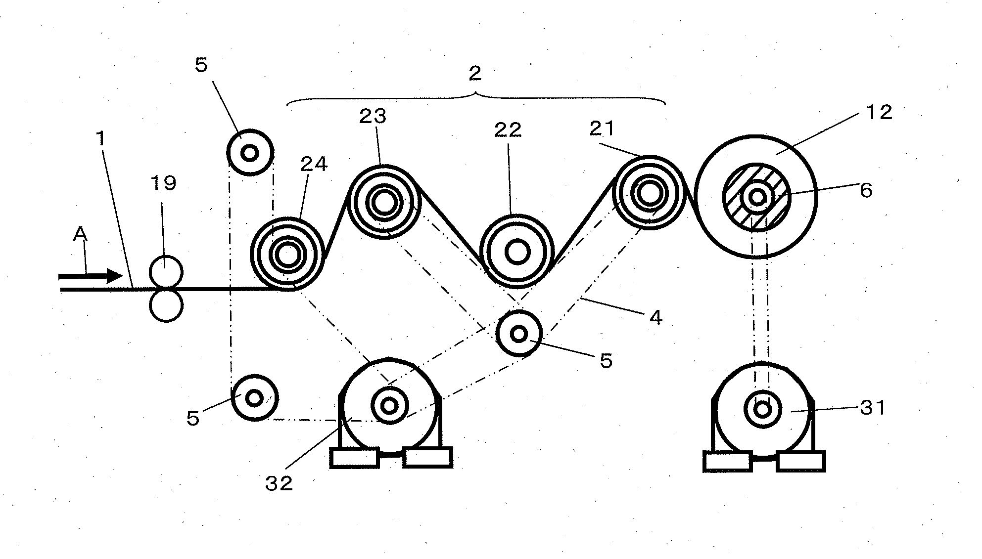
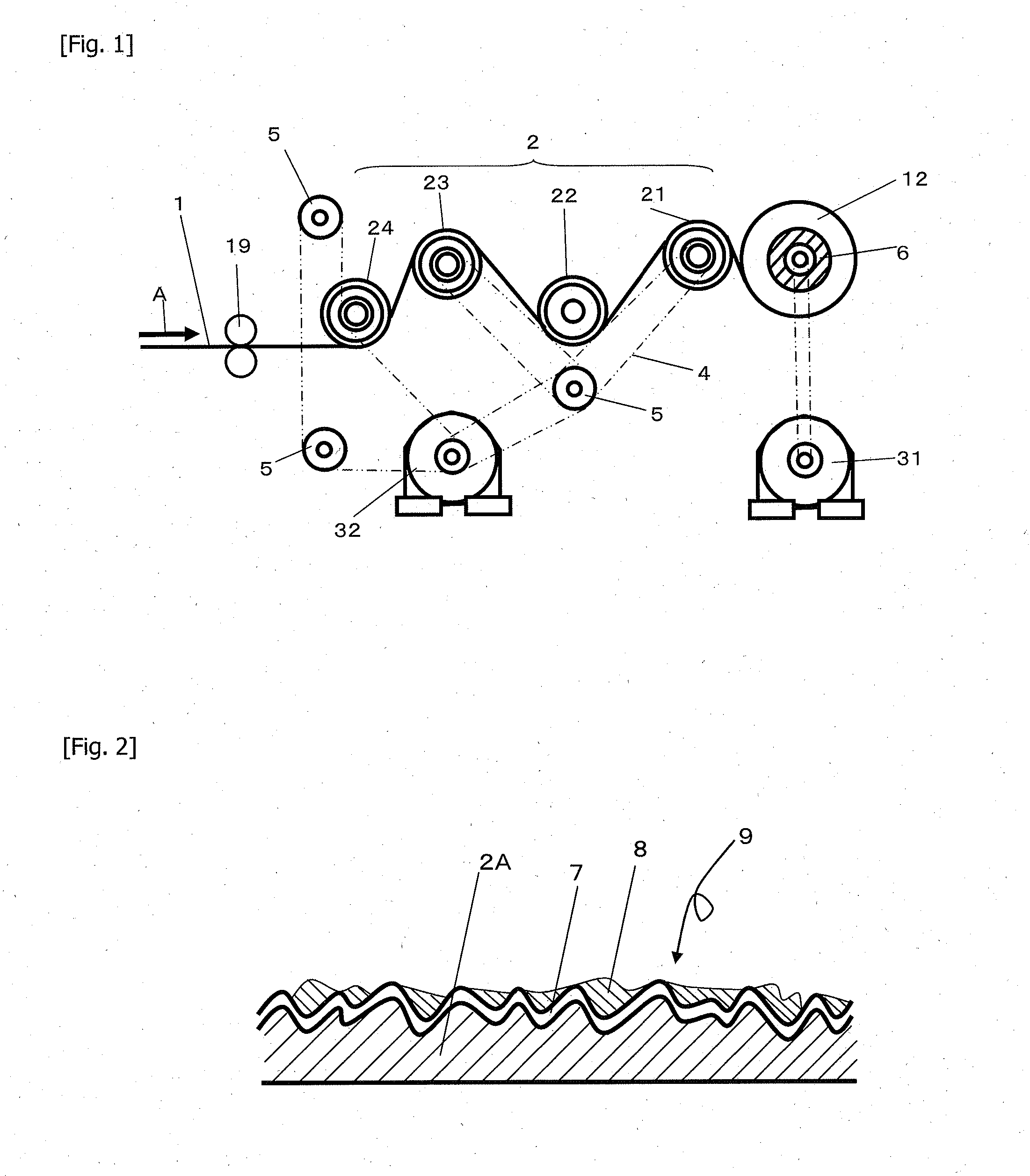
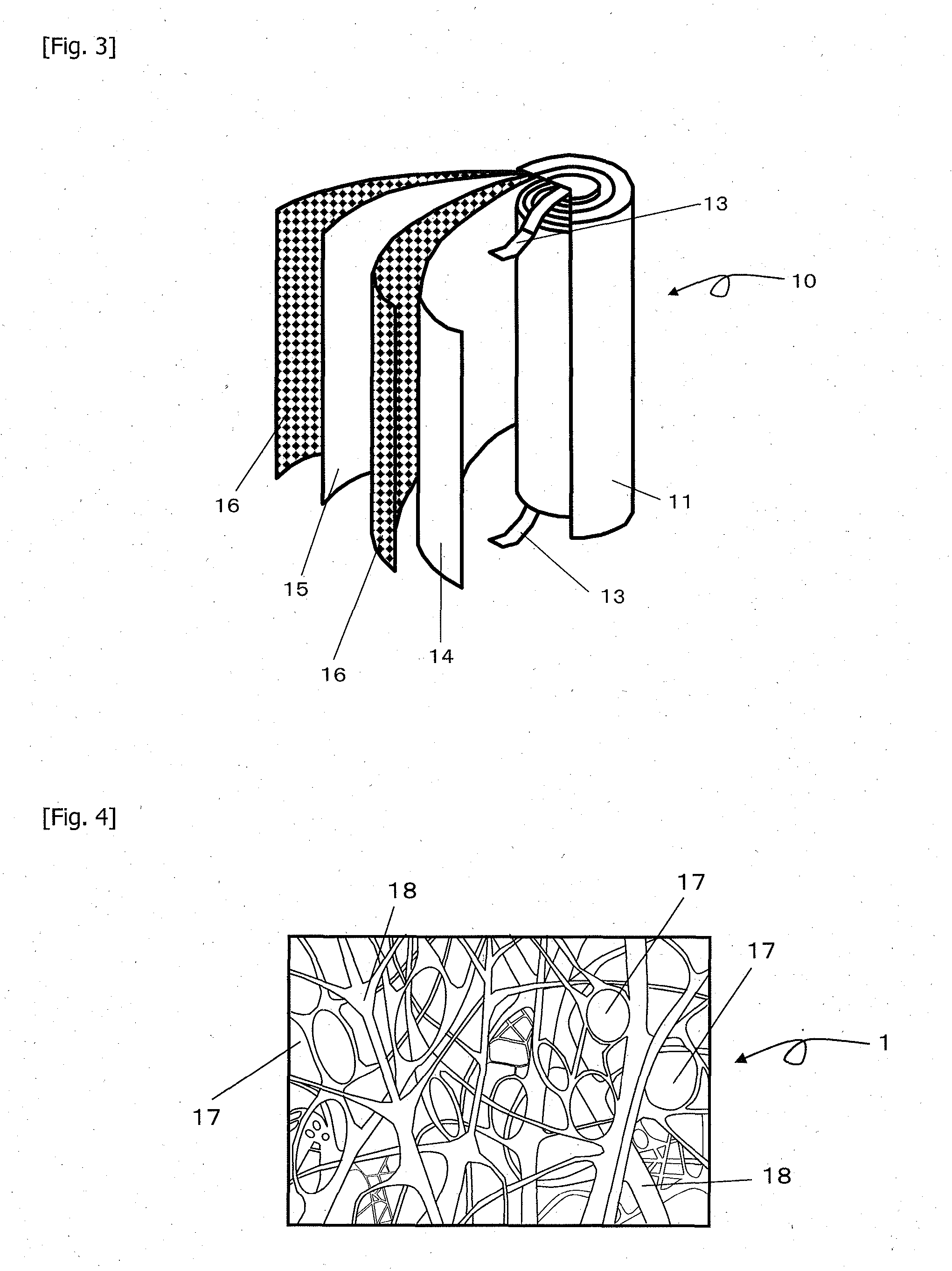
[0096]A microporous plastic film 1 of polypropylene in which through-holes as illustrated in FIG. 4 were formed by carrying out a biaxial stretching step while controlling the crystal structure of polypropylene was conveyed by a conveyance roller 2 as illustrated in FIG. 1 and wound up continuously on a core 6 to produce a microporous plastic film roll 12. The microporous polypropylene film had a Gurley air permeation resistance of 500 seconds per 100 ml, porosity of 70%, average pore size of 100 nm, and cushion rate of 17%. The film 1 had a width of 600 mm and thickness of 60 μm. The thickness was measured with an emitting / receiving type laser sensor, and the porosity was calculated by formula 6 from the measured thickness.

[0097]Here, the gas permeability is represented by the Gurley air permeation resistance (seconds per 100 ml) as specified in MS P8117 (2001). The Gurley air permeation resistance is defined as the time period required by 100 ml of air pressured under a constant p...

example 2

[0105]A film 1 with a thickness of 20 μm was wound up under the same conditions as in Example 1 to provide a microporous plastic film roll 12. The film had subsequently the same porosity as in the example, but its Gurley air permeation resistance was 100 seconds per 100 ml as a result of a smaller thickness.

example 3

[0106]The same procedure as in Example 2 was carried out except that a composite film of metal and polytetrafluoroethylene (PTFE) was formed on the surfaces of the conveyance rollers 21 to 24 as illustrated in FIG. 2 so that the portions of the four rollers coming in contact with the film 1 had a coefficient of static friction of 0.5 or less. To represent the surface roughness of the roller surfaces, their ten-point average roughness was measured under the same conditions as in Example 1.


PUM

PropertyMeasurementUnit
porosityaaaaaaaaaa
micropore sizeaaaaaaaaaa
thicknessaaaaaaaaaa

Abstract

A microporous plastic film roll production method, comprising the steps of: conveying microporous plastic film having through-holes in its interior by using a plurality of conveyance rollers at least one conveyance roller of which has a surface roughness RzJIS (μm) of 0.3≦RzJIS≦30 and has a surface made of fluorine resin, silicone rubber, or a composite material containing one of them; and winding it up in a roll.

Description

CROSS REFERENCE TO RELATED APPLICATIONS[0001]This application is the U.S. National Phase application of PCT / JP2012 / 057311, filed Mar. 22, 2012, and claims priority to Japanese Patent Application No. 2011-074642, filed Mar. 30, 2011, the disclosures of both applications being incorporated herein by reference in their entireties for all purposes.FIELD OF THE INVENTION[0002]The present invention relates to a method of manufacturing a microporous plastic film roll.BACKGROUND OF THE INVENTION[0003]For conventional processes in which a microporous plastic film for separators of secondary batteries and the like is conveyed and wound up into a roll, it has been very difficult to prevent wrinkle and breakage attributable to micropores.[0004]Non-patent document 1 theoretically determines the critical wrinkling values of general films and proposes a prevention method under the title “Prevention of wrinkle”. According to this reference, the critical wrinkling value is represented in terms of te...

Claims


Application Information

Patent Timeline
Patent Type & Authority Applications(United States)
IPC IPC(8): B65H18/08H01M50/403H01M50/414H01M50/489H01M50/491
CPCB65H18/08B65H27/00B65H2404/18B65H2404/531B65H2511/135B65H2701/1718B65H2701/1752H01G11/52B65H18/10B65H2401/111Y02E60/10H01M50/44H01M50/403H01M50/491H01M50/414H01M50/489H01G9/02H01M50/409Y02E60/13
Inventor ICHINOMIYA, TAKASHIMATSUMOTO, TADASHI
Owner TORAY IND INC
Why Eureka
Try Eureka