Thread-forming screw

a technology of threads and screws, applied in the direction of thread fasteners, screws, fastening means, etc., can solve the problem of insignificant melting of the base material of the screw, and achieve the effect of reducing the intermixing hardness, simple and cost-effective manufacturing of inventive screws, and reducing material corrosion resistan

Active Publication Date: 2009-02-03
HILTI AG
View PDF10 Cites 11 Cited by
  • Summary
  • Abstract
  • Description
  • Claims
  • Application Information

AI Technical Summary

Benefits of technology

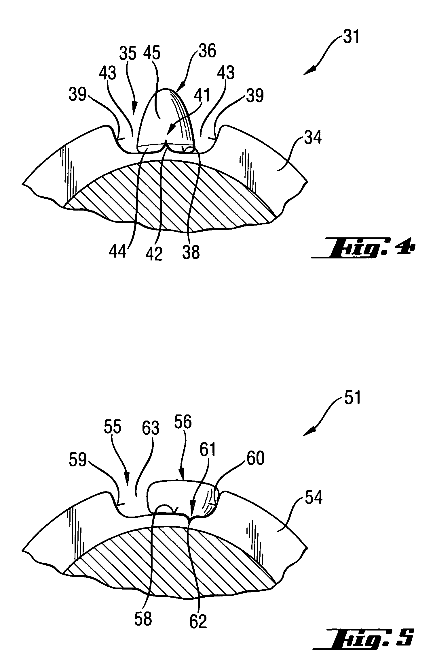
[0013]In the preliminary formed recesses, the weld beads can be formed in the thread with a carbon content sufficient for retaining their cutting capability. The possibility to form the weld beads with a desired carbon content leads to a better welding process and to a smaller tension between the base material and the weld deposits. The reduction of thermal stresses of the base material during formation of the weld beads provides for retention of the corrosion resistance of the base material to a most possible extent. Also, the formation of weld beads of a filler material permits to obtain more precise profile geometries with a finely defined geometry, which permits to obtain an advantageous cutting behavior in a mineral constructional materials, e.g., concrete. In addition, an expensive mechanical treatment of the produced cutting elements can be eliminated. The produced cutting elements can be formed as a part of the thread or project radially beyond the thread. Upon arrangement of several cutting elements along the course of the thread, the cutting elements, which are arranged adjacent to the setting direction end of the stem, can be so arranged that they project radially beyond the thread, with their radial extent being continuously reduced until it corresponds to the radial extent of the thread. According to an advantageous embodiment of the inventive, thread-forming screw, only in the region starting from the setting direction end of the stem, there can be provided from 4 to 15 spaced from each other, cutting elements.
[0025]E.g., in order to provide a first point on the recess bottom, e.g., in the region of the positioning element for positioning of a cutting element, a weld pool is formed, and then the filler material is fed into the pool and is slightly cooled. During an upward movement of the laser welding head, a portion of the filler material is fed again, and a second weld point is formed over the not yet solidified first weld point. With this process, intermixing between the cutting element and the core material of the screw is significantly reduced. Thereby, a sufficient hardness of the cutting element, together with retention of the corrosion resistance of the screw, is obtained.

Problems solved by technology

Therefore, only a very insignificant melting of the base material of the screw takes place.

Method used


Image

  • Thread-forming screw
  • Thread-forming screw
  • Thread-forming screw

Examples


Embodiment Construction

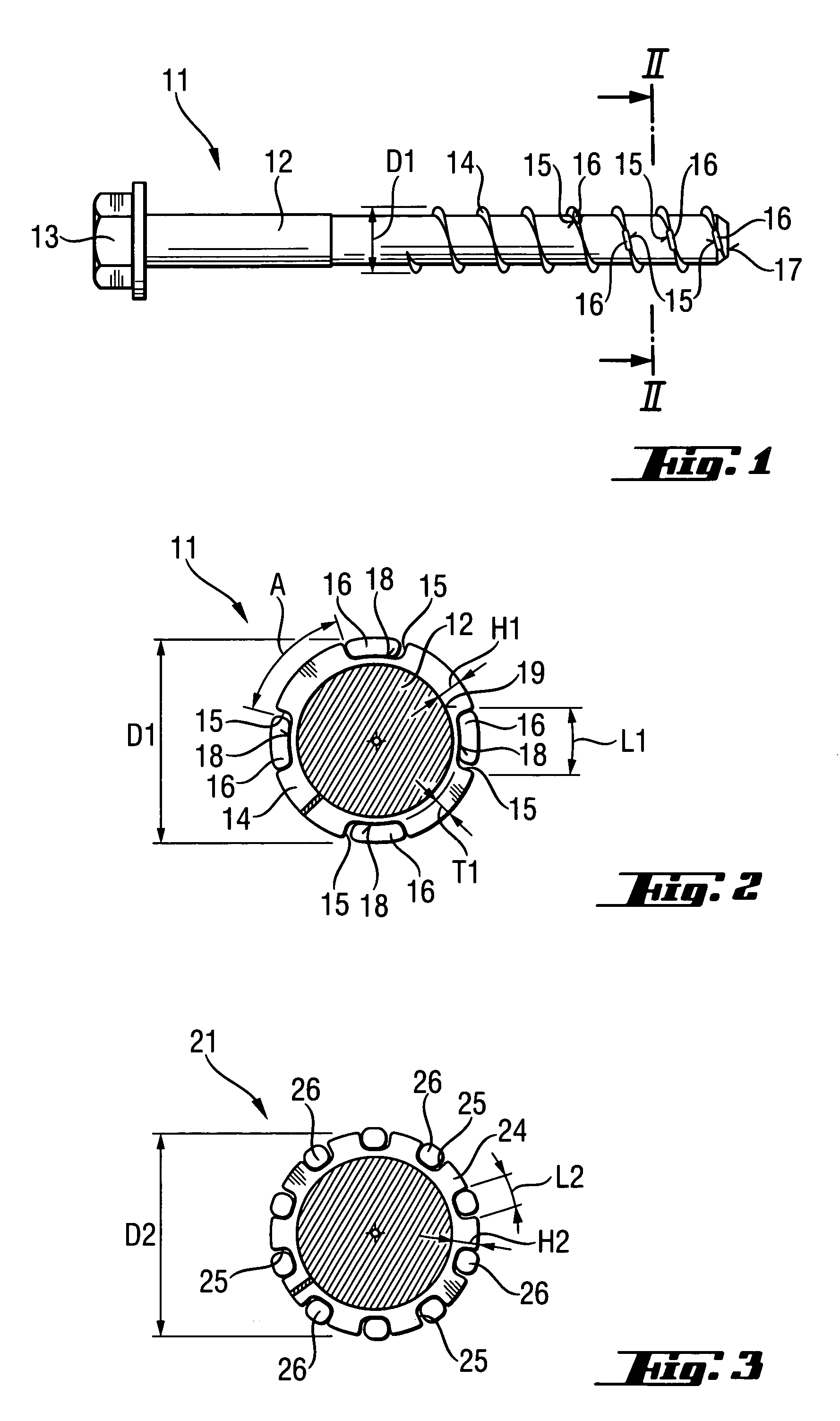
[0034]A corrosion-resistant, thread-forming screw 11 according to the present invention, which is shown in FIGS. 1-2, is formed of a base material containing, by weight, less than 0.5% of carbon, e.g., containing 0.1% of carbon, and has a stem 12, a screw head 13 provided at one end of the stem 12, and a thread 14 provided regionwise on the circumference of the stem 12. On the thread 14, there are formed a plurality of recesses 15 which are formed as linear recesses and in which weld beads are alloyed up to form cutting elements 16. The weld beads have a carbon content, by weight, of less than 0.8%, e.g., a carbon content of 0.7%. The angular distance A of the recesses 15 from each other and, thus, of the cutting elements 16 from each other along the course of the thread 14 increases, staring from the setting direction end 17 of the stem 12. The recesses 15 have a longitudinal extent L1 in the direction of the course of the thread 14 that corresponds to a triple of a radial extent H...


PUM


Abstract

A thread-forming screw (11; 21; 31; 51), has a stem (12) with at least one thread (14; 24; 34; 54) arranged, at least regionwise, over its circumference, and a plurality of cutting elements (16; 26; 36; 56) arranged in a respective plurality of recesses (15; 25; 35; 55) formed in the at least one thread (14; 24; 34; 54), with the cutting elements (16; 26; 36; 56) having a hardness greater than a hardness of the at least one thread (14; 24; 34; 54) and formed as weld beads received in the recesses (15; 25; 35; 55).

Description

BACKGROUND OF THE INVENTION[0001]1. Field of the Invention[0002]The present invention relates to a thread-forming screw, in particular, to a thread-forming screw produced of a corrosion-resistant metal and having a stem, at least one thread arranged, at least regionwise, over a circumference of the stem, and a plurality of cutting elements arranged in a respective plurality of recesses formed in the at least one thread, the cutting elements having a hardness greater than a hardness of the at least one thread.[0003]2. Description of the Prior Art[0004]Thread-forming screws of the type described above have a stem at one end of which, there is provided a head that serves as load application means. In thread-forming screws or thread-cutting screws, the outer thread has a high strength which permits to form a female thread in a constructional component. To this end, at least the steel of the outer thread is hardened. For external applications, the screws, such as concrete screws, are for...

Claims


Application Information

Patent Timeline
Patent Type & Authority Patents(United States)
IPC IPC(8): F16B25/10
CPCF16B25/0026F16B25/0052F16B33/06
Inventor WIESER, JUERGENLENNARTSSON, JOHANHOHMEIER, PIERREHUBER, FRANZ
Owner HILTI AG
Why Eureka
Try Eureka