Chain drive tensioner spring force control mechanism

Active Publication Date: 2014-07-03
BORG WARNER INC
View PDF26 Cites 9 Cited by
  • Summary
  • Abstract
  • Description
  • Claims
  • Application Information

AI Technical Summary

Benefits of technology

[0008]A tensioner which adjusts the mean tensioner force to keep the chain tension as low as possible without sacrif

Problems solved by technology

When tension in the chain increases during operation due to resonance of a chain span, a high load from the chain acts on the piston of the tensioner, causing the piston to retract into the housing of

Method used


Image

  • Chain drive tensioner spring force control mechanism
  • Chain drive tensioner spring force control mechanism
  • Chain drive tensioner spring force control mechanism

Examples


Example

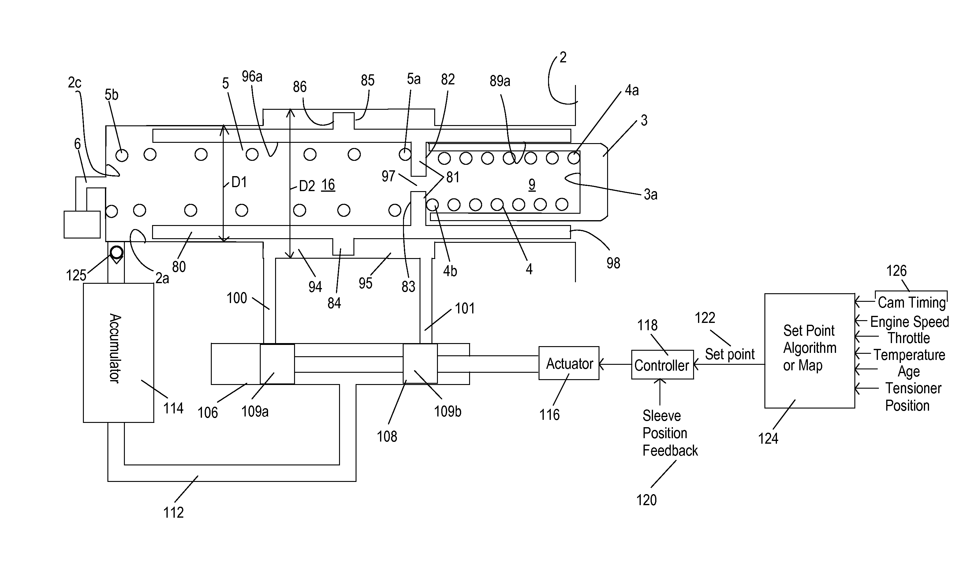
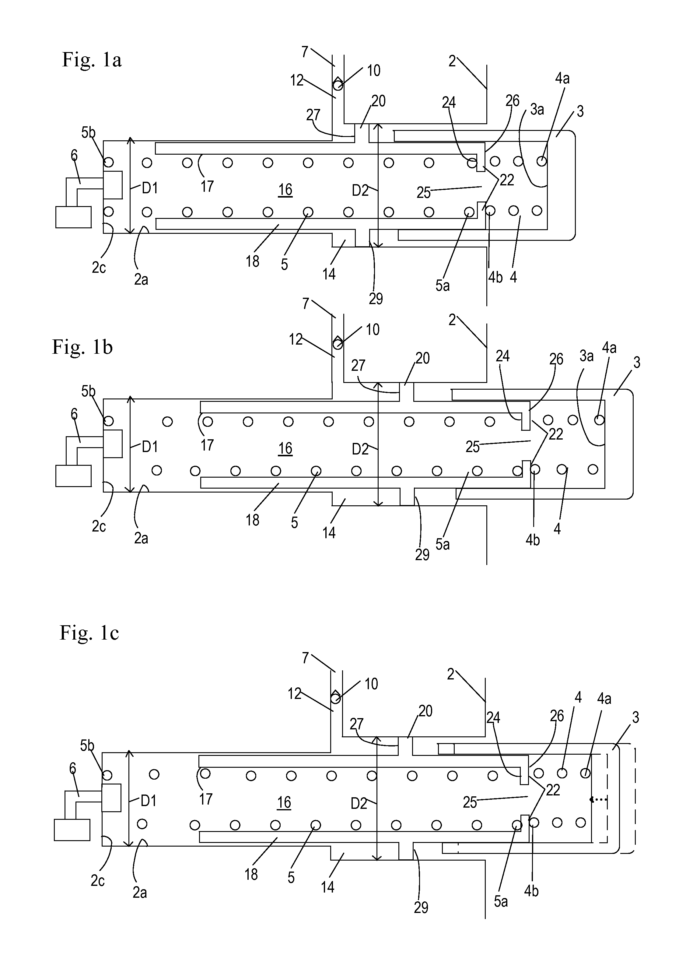
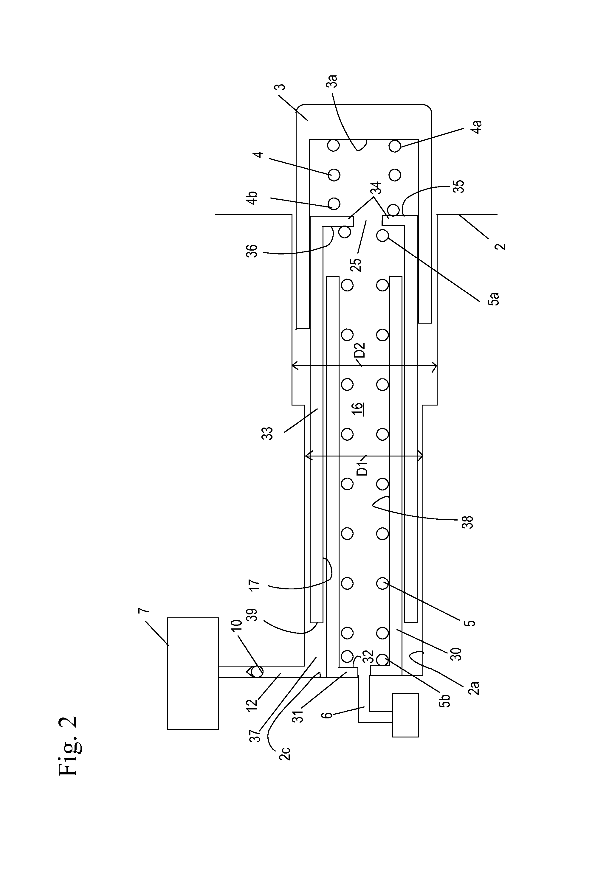
[0031]FIGS. 1a-8, 11-15, and 18a-22c show tensioner systems using passive control to maintain the position of a moveable sleeve relative to a piston. Passive control is defined as a system in which no feedback is used to regulate the position of a movable sleeve relative to a piston of the tensioner. In contrast, FIGS. 9 and 10 are active control systems in which real time feedback of components of the engine and / or the moveable sleeve itself are used to regulate the position of the sleeve.

[0032]The tensioner systems includes a tensioner (described in further detail below) for a closed loop chain drive system used in an internal combustion engine. It may be utilized on a closed loop power transmission system between a driveshaft and at least one camshaft or on a balance shaft system between the driveshaft and a balance shaft. The tensioner system may also include an oil pump and be used with fuel pump drives. Additionally, the tensioner systems may also be used with belt drives. The...


PUM


Abstract

A tensioner which adjusts the mean tensioner force to keep the chain tension as low as possible without sacrificing chain control, significantly improving drive efficiency as the chain wears and is subject to low dynamic loads.

Description

REFERENCE TO RELATED APPLICATIONS[0001]This application claims priority from International Application No. PCT / US2012 / 053830, entitled “CHAIN DRIVE TENSIONER SPRING FORCE CONTROL MECHANISM, which was filed on Sep. 6, 2012, which claims the benefit of Provisional Application No. 61 / 537,651, entitled, “CHAIN DRIVE TENSIONER SPRING FORCE CONTROL MECHANISM, filed Sep. 22, 2011; and also claims priority from International Application No. PCT / US2014 / 019329, entitled, “CHAIN DRIVE TENSIONER SPRING FORCE CONTROL MECHANISM filed Feb. 28, 2014. This application also claims the benefit of Provisional Application No. 61 / 772,673 filed Mar. 5, 2013, entitled “CHAIN DRIVE TENSIONER SPRING FORCE CONTROL MECHANISM”. The aforementioned applications are hereby incorporated herein by reference.BACKGROUND OF THE INVENTION[0002]1. Field of the Invention[0003]The invention pertains to the field of tensioners. More particularly, the invention pertains to chain drive tensioner spring force control mechanism...

Claims


Application Information

Patent Timeline
IPC IPC(8): F16H7/08
CPCF16H7/08F16H2007/0812F16H2007/0891F16H7/0848F16H2007/0814F16H2007/0859F16H2007/0817H05K999/99
Inventor TODD, KEVIN B.PATTON, MARK E.SMITH, DALE N.
Owner BORG WARNER INC
Why Eureka
Try Eureka