Lens driving device

Active Publication Date: 2017-02-16
HUIZHOU SAGETECH OPTRONICS CO LTD
View PDF5 Cites 1 Cited by
  • Summary
  • Abstract
  • Description
  • Claims
  • Application Information

AI Technical Summary

Benefits of technology

[0024]The present invention aims to provide a lens driving device with auto focus and shaking correction funct

Problems solved by technology

In recent years, mobile phones have various functions of internet communication, games and the like besides photographic function (cameras), so that the power consumption is increased.
Moreover, in electromagnetic drive type lens driving device used for cameras, besides the function of auto focus, the structure with the function of shaking correction is also added, and the power consumption in the lens driving device is also increased.
However, in the elect

Method used


Image

  • Lens driving device
  • Lens driving device
  • Lens driving device

Examples


Example

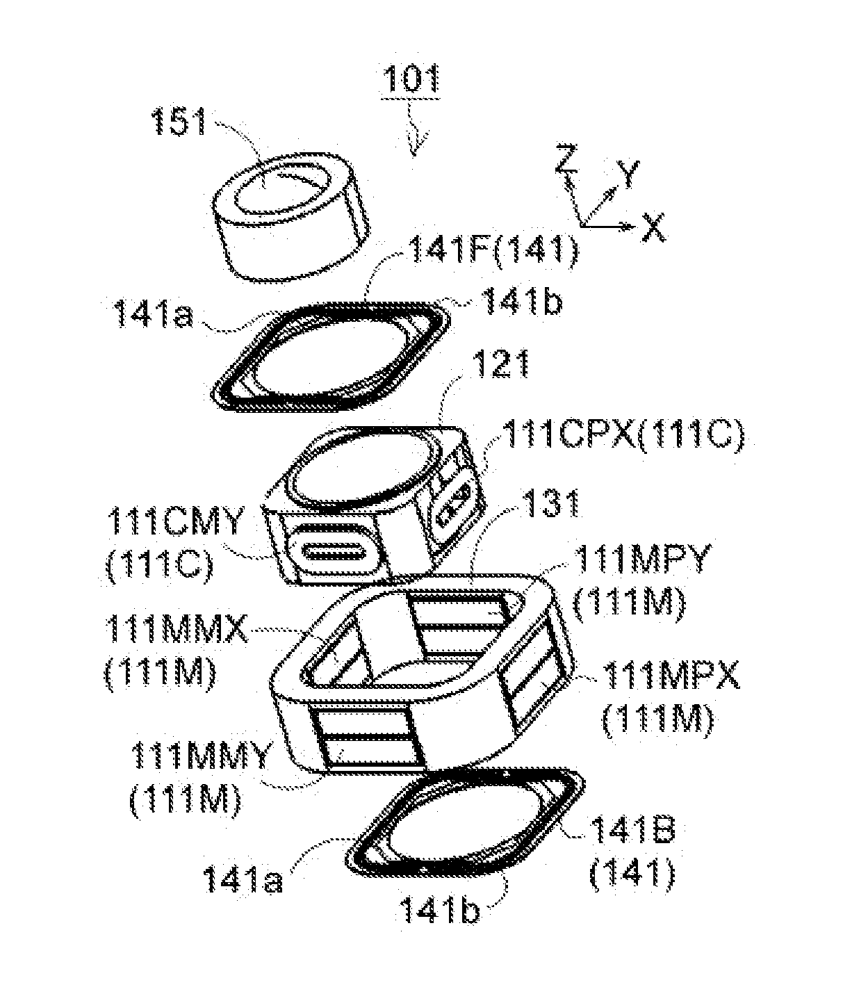
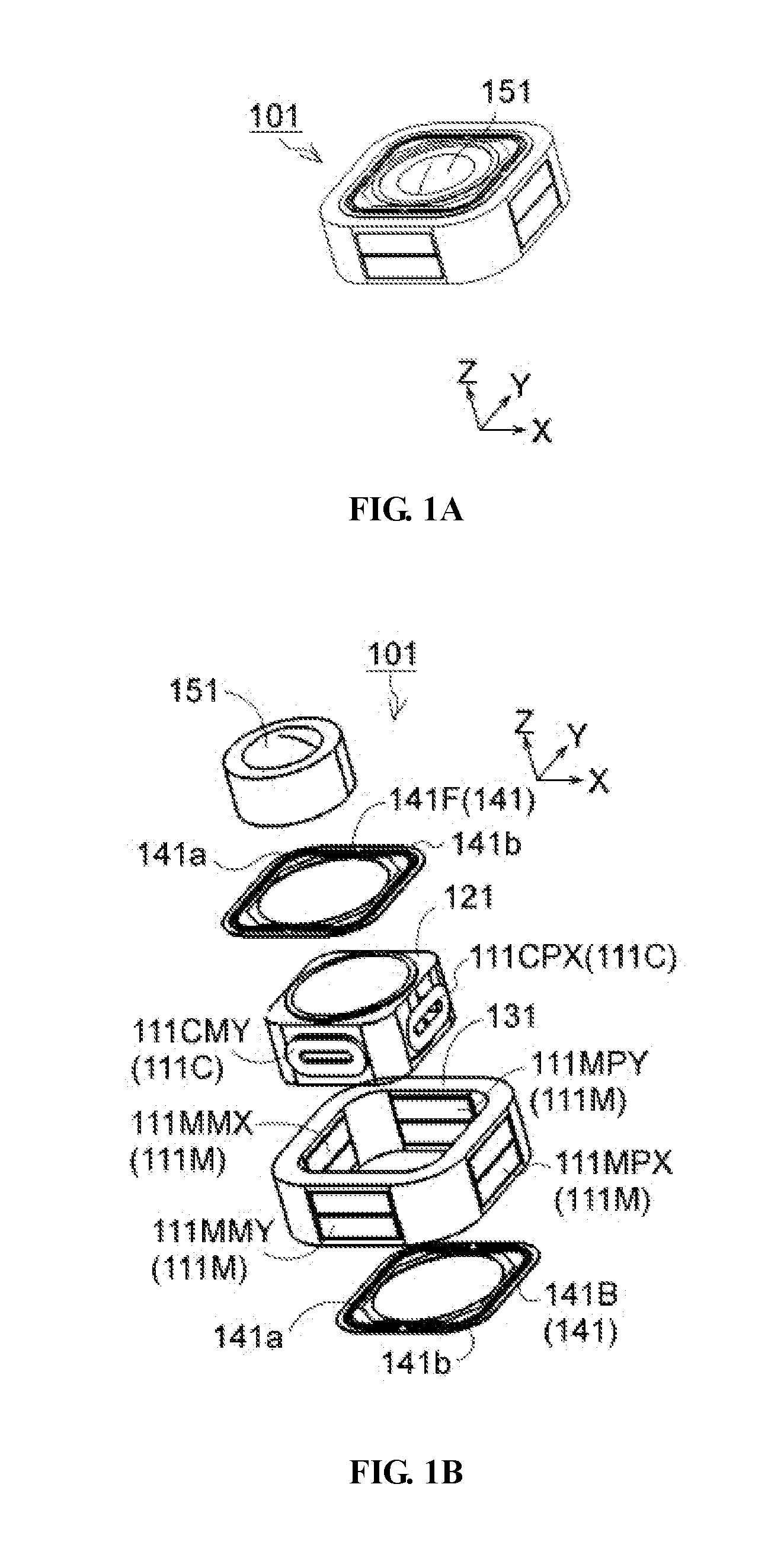
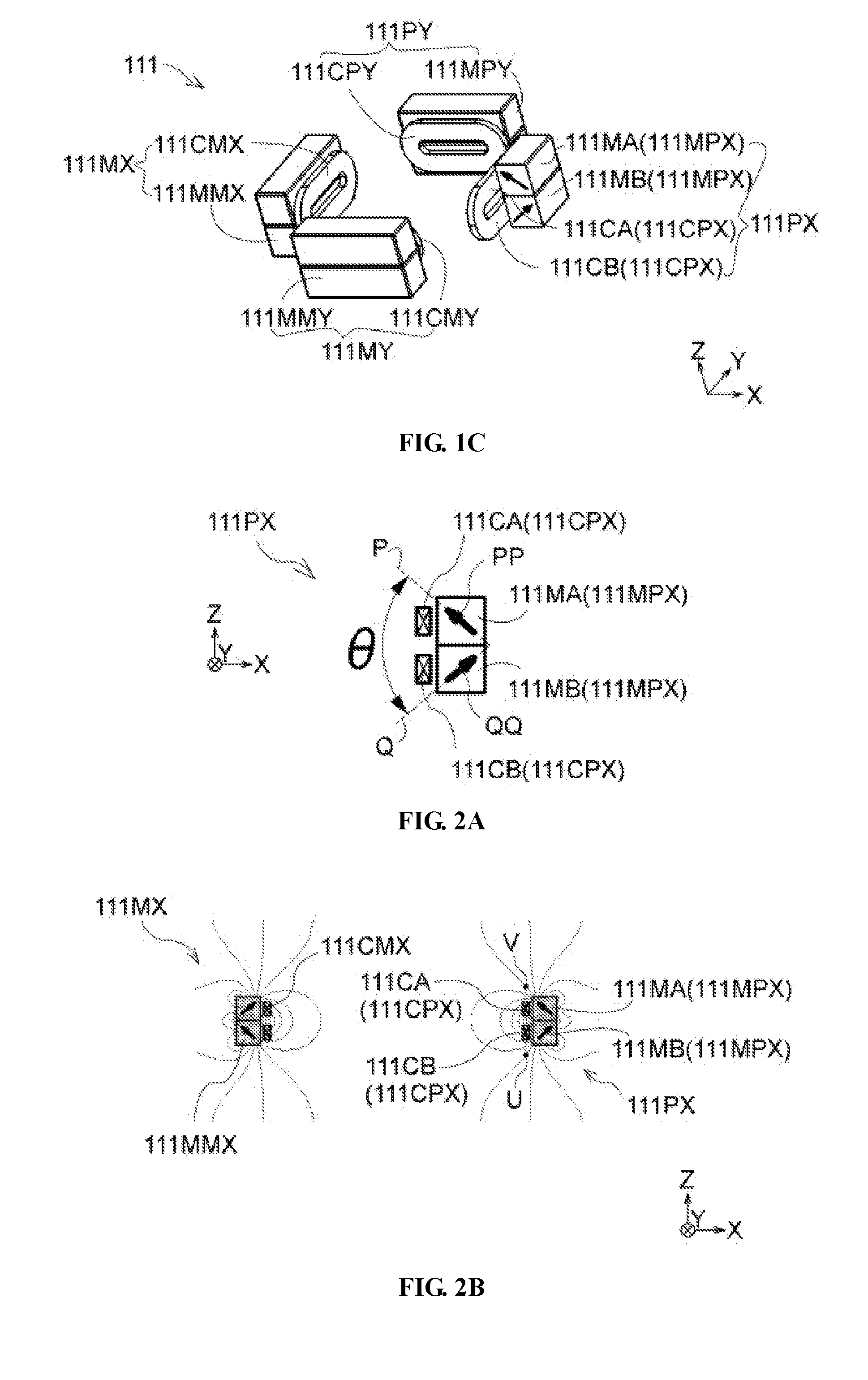
[0056]FIG. 1A is a perspective view of a lens driving device 101 in the first embodiment of the present invention. FIG. 1B is an exploded view of the lens driving device 101. FIG. 1C is a perspective view of an electromagnetic drive mechanism 111 in the lens driving device 101. Moreover, FIG. 2A is a schematic diagram illustrating the magnetization of the magnets 111M used in the electromagnetic drive mechanism 111, FIG. 2B is a schematic diagram illustrating the dispersion of a magnetic field generated by the drive magnets 111M, and FIG. 2C is a curve graph illustrating the magnetic induction intensity crossed with the drive coils 111C. Hereon, the optical axis direction of a lens 151 is set to be the Z axis direction (an object to be shot is at +Z side of the Z axis direction), and two directions forming right angles with Z axis and perpendicular with each other are set to be X axis direction and Y axis direction. Moreover, in FIG. 1C, the +X side drive magnet 111MPX is partially ...

Example

[0089]In the second embodiment, the +Z side magnet plate 112MA and the −Z side magnet plate 112MB are magnetized slantly in the manner that the magnetization directions of the +Z side magnet plate 112MA and the −Z side magnet plate 112MB form a certain expanded angle towards a winding width direction (in the Z axis direction) of the +Z side drive coil 112CPZ and the −Z side drive coil 112CMZ. And then, on the inner diameter side of the electromagnetic drive mechanism 112, the magnetic induction lines sent from the +Z side magnet plate 112MA are expanded towards the inner side of the electromagnetic drive mechanism 112 and are crossed with the +Z side drive coil 112CPZ; and after the magnetic induction lines are changed in the outer diameter direction of the electromagnetic drive mechanism 112, the magnetic induction lines are crossed with the −Z side drive coil 112CMZ and are returned to the −Z side magnet plate 112MB. Moreover, on the outer diameter side of the electromagnetic driv...

Example

[0111]Thus, in the lens driving device 103 in the third embodiment, the electromagnetic drive mechanism 113 for shaking correction can also utilize strong driving force, so that the lens maintained on the lens support 123 efficiently and straightly swings in the X axis direction and the Y axis direction respectively.

[0112]FIG. 5A is a main local space diagram of the electromagnetic drive mechanism 174 for focus and the electromagnetic drive mechanism 114 for shaking correction of the lens driving device 103 in the fourth embodiment of the present invention. Moreover, FIG. 5B is a magnetic figure illustrating a magnetic field generated by dual-purpose drive magnets 114M, and FIG. 5C is a diagram illustrating the magnetic induction intensity of the shaking correction coils 113 as shown in FIG. 4B. Moreover, only the part different from the lens driving device 103 in the third embodiment is illustrated in FIG. 5A, thus also refers to FIG. 4A and FIG. 4B in the following specification. ...


PUM


Abstract

The present invention aims to provide a lens driving device capable of realizing the reduction of power consumption by improving the driving efficiency of an electromagnetic drive mechanism. The lens driving device includes: one or mores drive coils having one or more forward path sides and one or more return path sides, and drive magnets each having a forward path side magnet plate and a return path side magnet plate. The magnetization directions of the forward path side magnet plate and the return path side magnet plate of each drive magnets define an angle which is expanded towards the oppositely arranged one or more drive coils. The magnetic induction intensity applied to the drive coils from the drive magnets can be increased and improved, and thus powerful lorentz force can be effectively generated by the drive coils after being electrified.

Description

BACKGROUND OF THE INVENTION[0001]1. Field of the Invention[0002]The present invention relates to a lens driving device used by a camera loaded in a mobile phone.[0003]2. Description of Related Art[0004]In recent years, mobile phones have various functions of internet communication, games and the like besides photographic function (cameras), so that the power consumption is increased. Moreover, in electromagnetic drive type lens driving device used for cameras, besides the function of auto focus, the structure with the function of shaking correction is also added, and the power consumption in the lens driving device is also increased.[0005]PCT patent application publication NO. WO2010 / 043078A1, Pub. date of Apr. 22, 2010 discloses a lens driving device as shown in FIG. 6A to 6D. FIG. 6A is a perspective view of a lens driving device 30, FIG. 6B is an exploded view of the lens driving device 30, FIG. 6C is a perspective view of the main parts of an electromagnetic drive mechanism 31 i...

Claims


Application Information

Patent Timeline
IPC IPC(8): G02B7/09H02K41/035G03B5/06G02B27/64G03B13/36
CPCG02B7/09G02B27/646G03B13/36G03B2205/0069H02K41/0356G03B2205/0023G03B5/06G03B5/00G02B7/08G03B3/10
Inventor TERAJIMA, KOKICHI
Owner HUIZHOU SAGETECH OPTRONICS CO LTD
Why Eureka
Try Eureka