
Device for driving working equipment of a commercial vehicle

Active Publication Date: 2012-06-21
ZF FRIEDRICHSHAFEN AG
View PDF2 Cites 2 Cited by
  • Summary
  • Abstract
  • Description
  • Claims
  • Application Information

AI Technical Summary

Benefits of technology

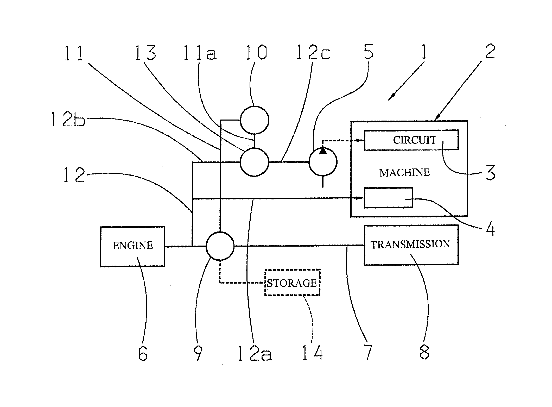
[0005]It is the task of the present invention to achieve, with a device for driving working equipment of an agricultural commercial vehicle of the above mentioned art, on one hand an independent drive rotational speed from the combustion engine for the working equipment, and on the other hand an improvement of the drive efficiency as compared to a pure electrical drive.
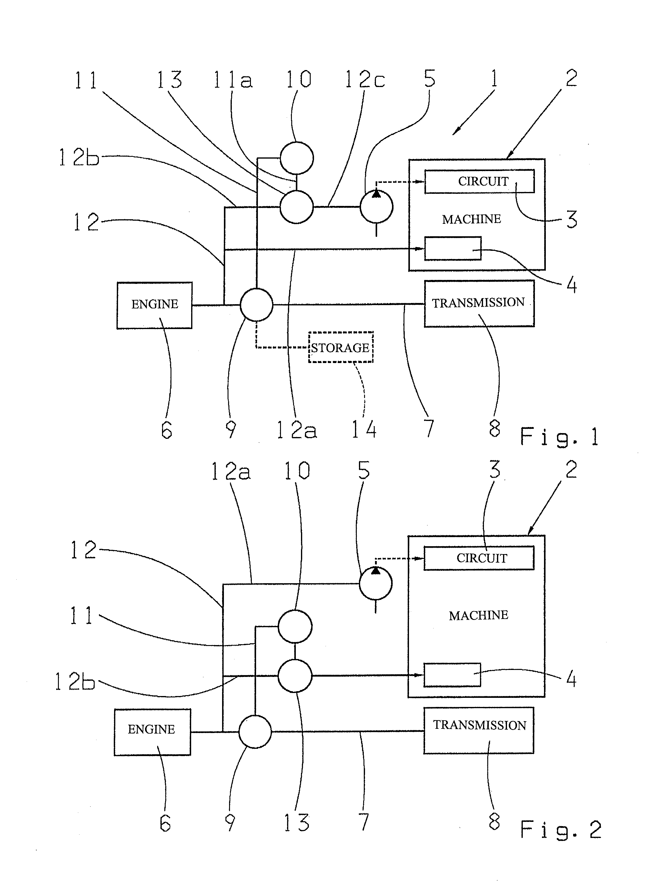
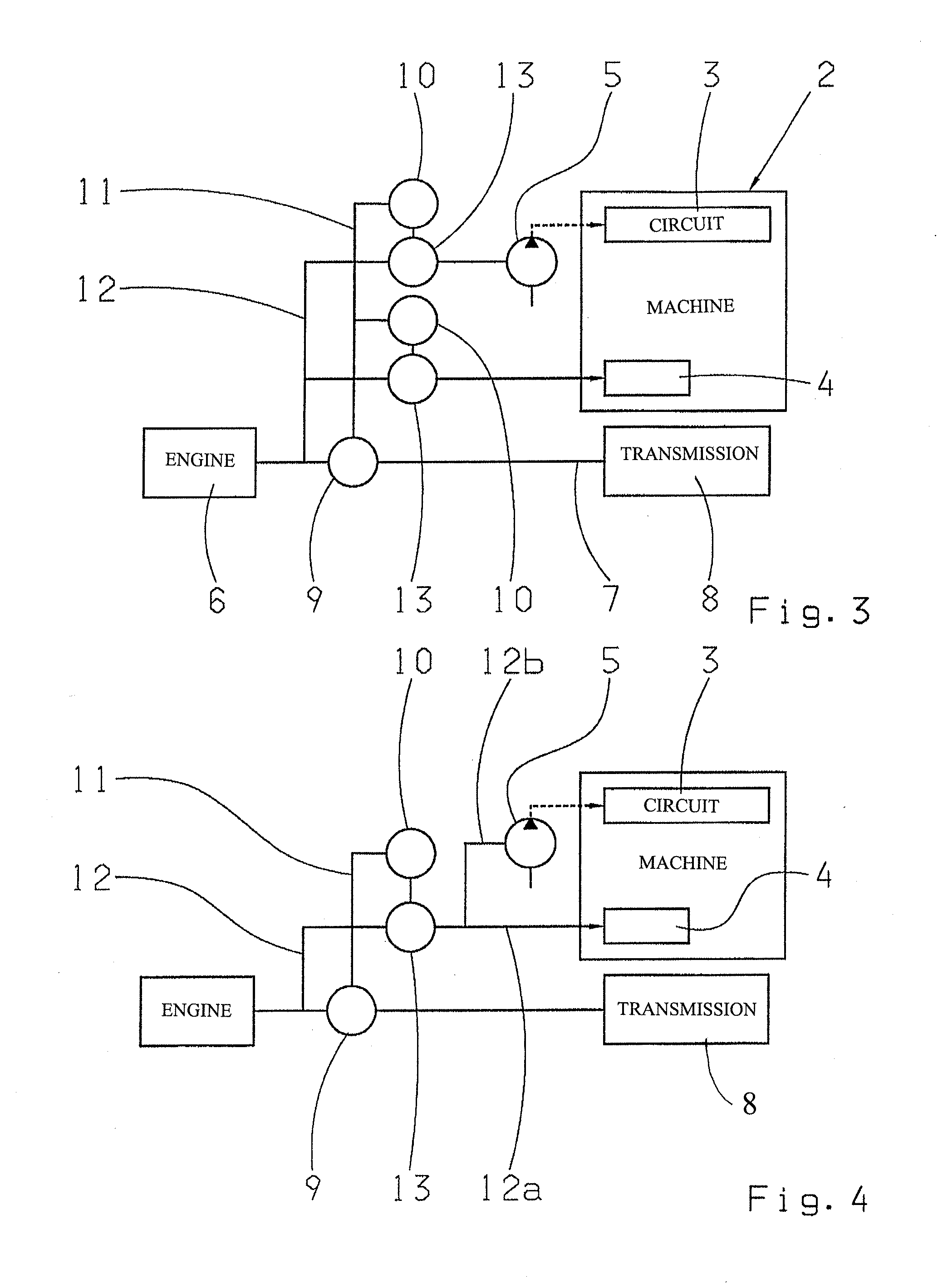
[0006]It is provided in accordance with the invention that the hydraulic pumps, positioned in the commercial vehicle or with the working equipment, and / or the mechanical connection, either electrically and / or mechanically, can be driven with a controllable rotational speed by means of power branching. The advantage hereby is that high efficiency is achieved through the partial mechanical drive and control of the rotational speed through the electrical drive, due to the power branching.
[0009]In an additional, preferred embodiment, the electric power branch has lower power than the mechanical power branch. This results in the advantage of a higher total efficiency for the drive of the working equipment.
[0010]In an additional, preferred embodiment, the control of the rotational speed takes place through the control of the electric power branch, meaning the mechanical power which is induced into the planetary transmission by the electric motor. Since there is only a small portion of the total power needed for the adjustment of the output rotational speed of the planetary transmission, this control results in advantages.
[0012]In an additional, preferred embodiment, the mechanical connection is driven through the planetary transmission, whereby it results in the advantage of the rotational speed control for the drive of the working equipment, and also, on the other hand, results in a relatively high efficiency because of the mechanical power branch.
[0013]In an additional, preferred embodiment, the hydraulic pumps as well as the mechanical connection can be driven by one or two planetary transmissions. In this case, the advantage is that the drive rotational speed of both users can be controlled.

Problems solved by technology

Disadvantageous is the dependence of the power take-off shaft rotational speed in relationship to the rotational speed of the motor which does not match the respective optimum rotational speed of the different working equipment.
However, it is a disadvantage that the total drive power for the planting device is induced as by electrical power which creates a decrease of the efficiency, meaning an increased gasoline consumption of the combustion engine of the tractor.

Method used


Image

  • Device for driving working equipment of a commercial vehicle
  • Device for driving working equipment of a commercial vehicle
  • Device for driving working equipment of a commercial vehicle

Examples


Embodiment Construction

[0028]FIG. 1 shows a device 1 for the drive of a working equipment 2 of an agricultural commercial vehicle, not shown here, called a tractor in the following. The working equipment 2 can be coupled, not shown here, to the tractor and can be exchanged, as required with other working equipment which performs different agricultural working functions. Thus, the connection of the working equipment 2 with the tractor can be detached. The working equipment 2 comprises one or more a hydraulic working circuits, for instance, for actuating lift equipment and for the working equipment itself. In addition the tractor can include a hydraulic circuit for providing the lubrication and system pressure to the transmission and the rear axle of the tractor. A hydraulic circuit is, in the example, marked with the reference number 3. The working equipment also comprises of a mechanical connection 4, for instance designed as a clutch for a mechanical drive of the working equipment 2, whereby the drive ta...


PUM


Abstract

A device (1) for driving working equipment (2) which can be connected to an agricultural commercial vehicle. The commercial vehicle has a combustion engine (6) and a generator (9) which can be driven by the combustion engine (6). The commercial vehicle and / or the working equipment (2) have at least a hydraulic pump (5), for the supply of a hydraulic working circuit (3), and a mechanical connection (4), for driving the working equipment (2). At least one hydraulic pump (5) and / or the mechanical connection (4) can be driven electrically and / or mechanically, and can be driven with a controllable rotational speed by way of the power branching.

Description

[0001]This application claims priority from German patent application serial no. 10 2010 063 568.5 filed Dec. 20, 2010.FIELD OF THE INVENTION[0002]The invention concerns a device for driving working equipment of an agricultural commercial vehicle.BACKGROUND OF THE INVENTION[0003]Agricultural commercial vehicles or tractors can be equipped with a multitude of different working or planting equipment which are used for different agricultural working functions. The working equipment is generally driven either mechanically or hydraulically, for instance by means of a so-called power take-off shaft, which is driven by the combustion engine of the tractor. Disadvantageous is the dependence of the power take-off shaft rotational speed in relationship to the rotational speed of the motor which does not match the respective optimum rotational speed of the different working equipment.[0004]Therefore, it has already been proposed to electrically drive the working equipment which is connected to...

Claims


Application Information

Patent Timeline
IPC IPC(8): F15B21/00B60L50/15
CPCA01B59/00B60K6/365B60K6/445
Inventor GOTZ, MANUELWEINMANN, OLRIKMOHR, MARKFELLMANN, MARTIN
Owner ZF FRIEDRICHSHAFEN AG
Learn More