Tuning bar piezoelectric vibrator and tuning fork piezoelectric vibrator

Inactive Publication Date: 2013-12-26
MURATA MFG CO LTD
View PDF16 Cites 0 Cited by
  • Summary
  • Abstract
  • Description
  • Claims
  • Application Information

AI Technical Summary

Benefits of technology

[0025]The tuning bar piezoelectric vibrator according to a preferred embodiment of the present invention is configured such that the first piezoelectric layer is sandwiched between the first outer electrode and the first and second inner driver electrodes that are separated from each other in the plane direction of the interface between the first and second piezoelectric layers. Furthermore, the second piezoelectric layer is sandwiched between the second outer electrode and the first and second inner driver electrodes. Thus, the piezoelectricity effect of both the first and second piezoelectric layers is utilized. Thus, for example, when the tuning bar piezoelectric vibrator according to a preferred embodiment of the present invention is used as a vibrator of vibrating gyroscope, the driving efficiency is improved. Furthermore, the first and second inner driver electrodes are the driver electrodes, and the first and second outer electrodes are provided on the outer surfaces of th

Problems solved by technology

Thus, driving efficiency is not sufficiently high.
For example, it is difficult to improve sensitivity when the device is used as a sensor for detecting the rotational angula

Method used


Image

  • Tuning bar piezoelectric vibrator and tuning fork piezoelectric vibrator
  • Tuning bar piezoelectric vibrator and tuning fork piezoelectric vibrator
  • Tuning bar piezoelectric vibrator and tuning fork piezoelectric vibrator

Examples


Embodiment Construction

[0045]Hereinafter, the present invention is disclosed in detail by describing specific preferred embodiments of the present invention with reference to the drawings.

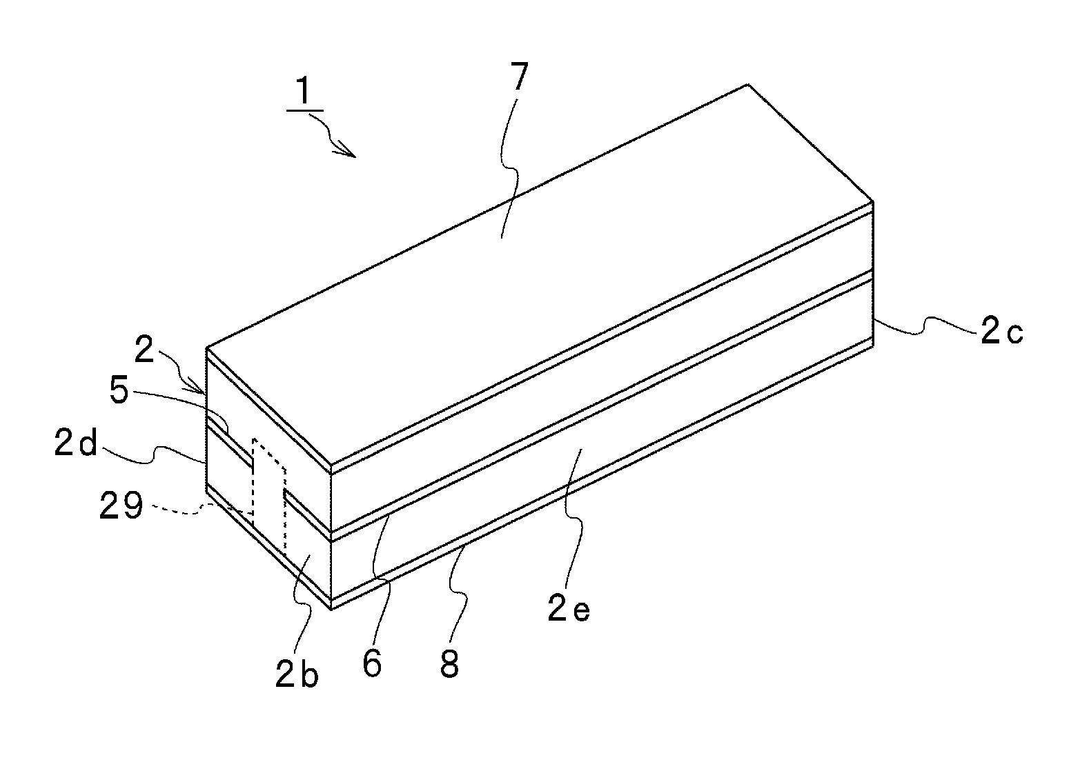
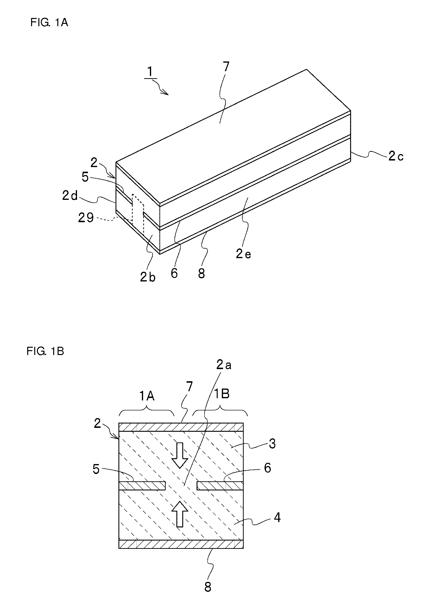
[0046]FIG. 1A and FIG. 1B are a perspective view and a cross-sectional view of a tuning bar piezoelectric vibrator according to a first preferred embodiment of the present invention.

[0047]A tuning bar piezoelectric vibrator 1 includes a long-and-narrow strip shaped piezoelectric body 2. In other words, the piezoelectric body 2 with a long-and-narrow rectangle planar shape is preferably used.

[0048]The piezoelectric body 2 is preferably made of piezoelectric ceramics such as PZT based ceramics. As illustrated in FIG. 1B, the piezoelectric body 2 includes a first piezoelectric layer 3 on the upper side and a second piezoelectric layer 4 on the lower side. A first inner driver electrode 5 and a second inner driver electrode 6 are provided at an interface between the first piezoelectric layer 3 and the second piezoelectric la...


PUM


Abstract

A tuning bar piezoelectric vibrator includes first and second leg portions defined by a tuning bar piezoelectric vibrator, layers of first and second inner driver electrodes arranged as inner driver electrodes between first and second piezoelectric layers that are polarized in opposite directions of a thickness direction, a first outer electrode and a second outer electrode arranged to face the first and the second inner driver electrodes with the piezoelectric layers in between, respectively, and first and second vibrator portions in which the inner driver electrodes are used as driver electrodes.

Description

BACKGROUND OF THE INVENTION[0001]1. Field of the Invention[0002]The present invention relates to piezoelectric vibrators, and more particularly to tuning bar piezoelectric vibrators and tuning fork piezoelectric vibrators, each of which includes first and second piezoelectric layers that are joined together so as that polarization directions thereof are opposite to each other in a thickness direction.[0003]2. Description of the Related Art[0004]In recent years, vibrating gyroscopes are widely used as anti-vibration sensors for digital cameras or rotational angular velocity sensor devices for automobile navigation. Conventionally, tuning fork piezoelectric vibrators are used as vibrators of such vibrating gyroscopes.[0005]International Publication No. WO 2007 / 125615 discloses one example of tuning fork piezoelectric vibrator for use in a vibrating gyroscope. FIG. 16A and FIG. 16B are a top view and a bottom view of the tuning fork piezoelectric vibrator described in International Pub...

Claims


Application Information

Patent Timeline
IPC IPC(8): G01C19/5607H01L41/107G01C19/5642H01L41/047
CPCG01C19/5607H01L41/047H01L41/107G01C19/5642H03H9/21H03H9/583H10N30/40H10N30/87
Inventor KURAKAWA, HARUYOSHI
Owner MURATA MFG CO LTD
Why Eureka
Try Eureka