

Magnetic tape and magnetic tape device
a technology of magnetic tape and magnetic head, which is applied in the field of magnetic tape and magnetic tape device, can solve the problems of difficult to properly follow the data of the magnetic head, and errors may easily occur at the time of recording and/or reproduction, and achieve the effect of improving the positioning accuracy of the head of a timing-based servo system
Active Publication Date: 2017-12-14
FUJIFILM CORP
View PDF0 Cites 110 Cited by
- Summary
- Abstract
- Description
- Claims
- Application Information
AI Technical Summary
Benefits of technology
The patent text describes a method for improving the accuracy of a magnetic tape device when recording and playing back magnetic signals. This is achieved by embedding a servo signal in a magnetic layer, which is read by a servo head to control the position of the magnetic head. By doing so, the system can better compensate for any changes in the position of the magnetic tape, ensuring accurate positioning of the magnetic head and proper recording and playback of the magnetic signals. This patent aims to provide a better performing magnetic tape and device for recording and playing back magnetic signals.
Problems solved by technology
However, when the width of the data track is narrowed and the recording and / or reproduction of magnetic signals is performed by allowing the running of the magnetic tape in a magnetic tape device (normally referred to as a “drive”), it is difficult that a magnetic head properly follows the data tracks in accordance with the position change of the magnetic tape in the width direction, and errors may easily occur at the time of recording and / or reproduction.
Method used
View moreImage
Smart ImageViewing Examples

Examples
examples
[0255]Hereinafter, the invention will be described with reference to examples. However, the invention is not limited to aspects shown in the examples. “Parts” and “%” in the following description mean “parts by mass” and “mass %”, unless otherwise noted.
[0256]An average particle size described below is a value measured by a method disclosed in paragraphs 0058 to 0061 of JP2016-071926A. The measurement was performed by using transmission electron microscope H-9000 manufactured by Hitachi, Ltd. as the transmission electron microscope, and image analysis software KS-400 manufactured by Carl Zeiss as the image analysis software.
Login to View More PUM
| Property | Measurement | Unit |
|---|---|---|
| magnetic | aaaaa | aaaaa |
| activation volume | aaaaa | aaaaa |
| magnetic force microscope | aaaaa | aaaaa |
Abstract
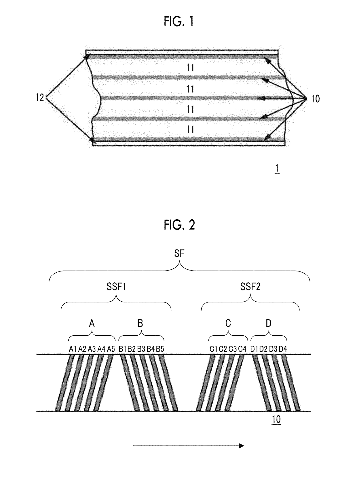
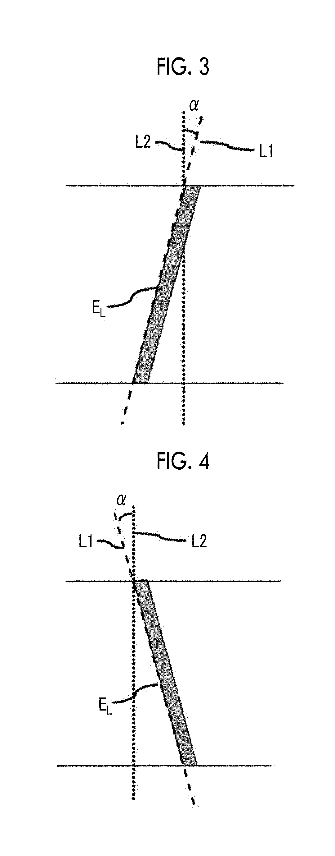
The magnetic tape includes a magnetic layer having ferromagnetic powder and a binder on a non-magnetic support, in which the magnetic layer includes a timing-based servo pattern, the ferromagnetic powder is ferromagnetic hexagonal ferrite powder having an activation volume equal to or smaller than 1,600 nm3, and an edge shape of the timing-based servo pattern specified by a magnetic force microscope observation is a shape in which a difference (l99.9−l0.1) between a value l99.9 of a cumulative frequency function of 99.9% of a position deviation width from an ideal shape in a longitudinal direction of the magnetic tape and a value l0.1 of the cumulative frequency function of 0.1% thereof is equal to or smaller than 180 nm.
Description
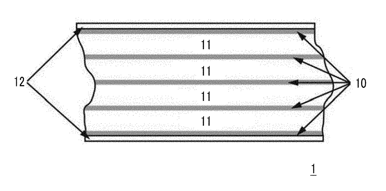
CROSS-REFERENCE TO RELATED APPLICATIONS[0001]This application claims priority under 35 U.S.C 119 to Japanese Patent Application No. 2016-117339 filed on Jun. 13, 2016. The above application is hereby expressly incorporated by reference, in its entirety.BACKGROUND OF THE INVENTION1. Field of the Invention[0002]The present invention relates to a magnetic tape and a magnetic tape device.2. Description of the Related Art[0003]Magnetic recording media are divided into tape-shaped magnetic recording media and disk-shaped magnetic recording media, and tape-shaped magnetic recording media, that is, magnetic tapes (hereinafter, also simply referred to as “tapes”) are mainly used for data storage such as data back-up or archive. The recording of information into magnetic tape is normally performed by recording a magnetic signal on a data band of the magnetic tape. Accordingly, data tracks are formed in the data band.[0004]An increase in recording capacity (high capacity) of the magnetic tape ...
Claims
Login to View More Application Information
Patent Timeline
 Patent Type & AuthorityApplications(United States)
IPC IPC(8): B22F9/16G11B5/008H01F1/03
CPCB22F9/16G11B5/00813C01P2004/64C01P2006/42C01P2004/03H01F1/0311G11B5/584G11B5/7023G11B5/70678H01F1/11B22F2007/047B22F7/04B22F2999/00C22C2200/02B22F2202/05G11B5/70615G11B5/714G11B5/78
InventorKANEKO, TETSUYAKASADA, NORIHITOOZAWA, EIKI
OwnerFUJIFILM CORP