Connector

a technology of connecting rods and connectors, applied in the direction of coupling contact members, coupling device connections, contacts, etc., can solve the problems that the electric power supplied to electrical apparatuses may affect human bodies or affect the operation of electronic components, so as to achieve the effect of safe supply of electric power

Inactive Publication Date: 2018-01-18
FUJITSU COMPONENENT LTD
View PDF8 Cites 1 Cited by
  • Summary
  • Abstract
  • Description
  • Claims
  • Application Information

AI Technical Summary

Benefits of technology

[0010]According to an embodiment of the present invention, a connector that supports direct-current power supplies or a power supply of a voltage higher than current commercial power supply voltages and is capable of safely supplying electric power from these power supplies can be provided.

Problems solved by technology

Electric power supplied to electrical apparatuses may affect human bodies or may affect the operations of electronic components if the voltage is high.

Method used


Image

  • Connector
  • Connector
  • Connector

Examples


first embodiment

(Connector Structure)

[0047]A connector according to a first embodiment is described.

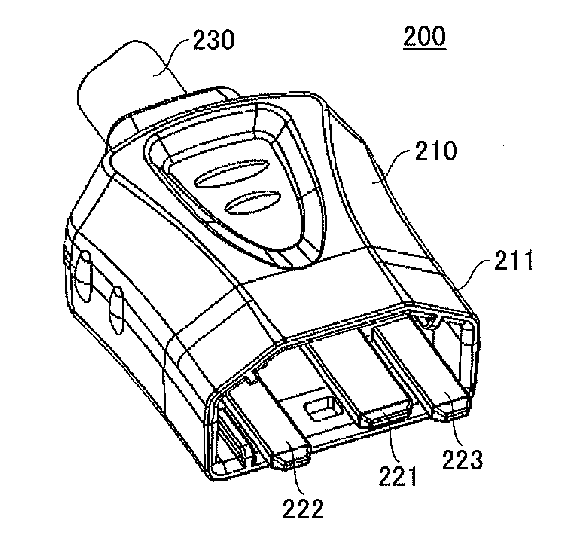
[0048]A connector 10 according to this embodiment is depicted in FIGS. 6 through 8, and is configured to be connected to a plug connector 200 depicted in FIGS. 1 through 5.

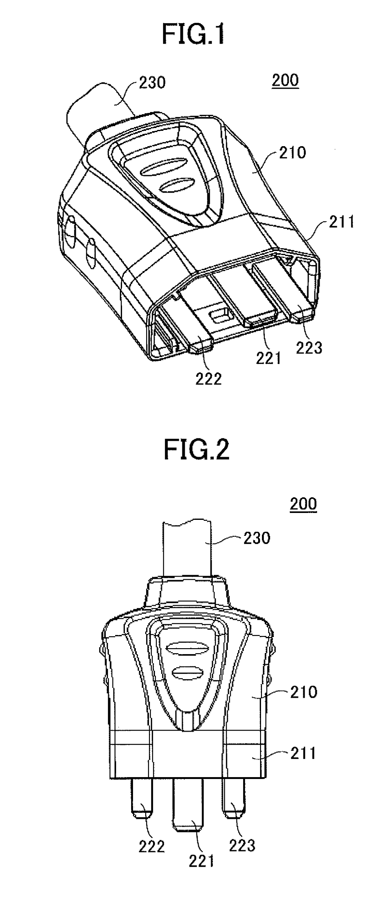
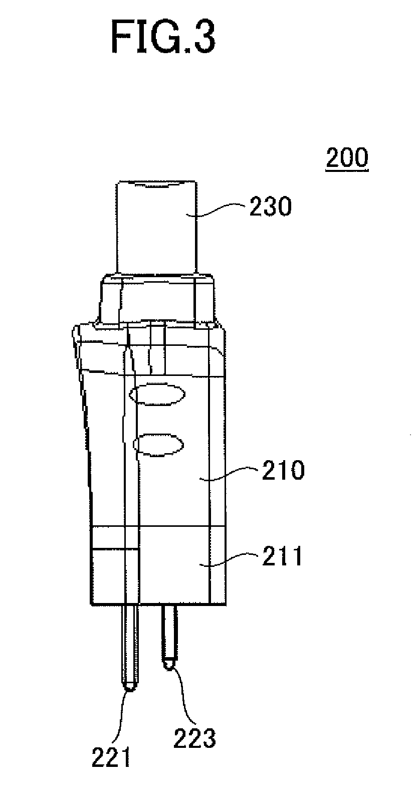
[0049]The plug connector 200 is described based on FIGS. 1 through 5. FIG. 1 is a perspective view, FIG. 2 is a plan view, FIG. 3 is a side view, FIG. 4 is a bottom view, and FIG. 5 is a front view of the plug connector 200.

[0050]The plug connector 200 includes a cover 210 formed of an insulator and three plug terminals 221, 222 and 223. A power supply cable 230 is connected to the cover 210 on the side opposite from the side on which the plug terminals 221, 222 and 223 are provided. The plug terminal 221 is a GND terminal, and is formed to be longer than the plug terminals 222 and 223. The plug terminals 222 and 223 are terminals configured to be electrically connected to terminals of the connector 10 to be supplied with electric ...

second embodiment

[0096]Next, a second embodiment is described. This embodiment is a structure where multiple movable contacts are provided in a single switch.

[0097]A switch according to this embodiment depicted in FIG. 33 includes a first switch 301a and a second switch 301b each including a movable part formed of a twin contact. As depicted in FIGS. 34 and 35, a first fixed part 310a and a second fixed part 310b, and a first movable part 320a and a second movable part 320b are provided in the switch.

[0098]The first fixed part 310a includes a first fixed contact 311a installed on a first fixed spring 312a. The second fixed part 310b includes a second fixed contact 311b installed on a second fixed spring 312b.

[0099]The first movable part 320a includes a first movable contact 321a and a second movable contact 321b. The first movable contact 321a is installed on a first movable plate 322a, and the second movable contact 321b is installed on a second movable plate 322b. The first movable plate 322a and...


PUM


Abstract

A connector includes two connection terminals to be electrically connected to terminals of another connector, and a switch connected to the connection terminals. The switch includes a first switch connected to one of the connection terminals, the first switch including a first fixed part including a fixed contact, and a first movable part including a movable contact that is contactable by the fixed contact, and a second switch connected to another of the connection terminals, the second switch including a second fixed part including a fixed contact, and a second movable part including a movable contact that is contactable by the fixed contact. The first fixed part and the second fixed part, or the first movable part and the second movable part include multiple contacts.

Description

TECHNICAL FIELD[0001]The present invention relates to connectors.BACKGROUND ART[0002]In general, electrical apparatuses are supplied with electric power via a connector. The connector used in this case establishes an electrical connection by mating together a male-ended connector having a protruding shape and a female-ended connector having an indented shape.[0003]In recent years, as a measure against global warming, the supply of direct-current high-voltage electric power, which is limited in power loss in voltage conversion or power transmission and does not require an increase in cable thickness, has been studied in power transmission in local areas as well. Such form of supplying electric power is considered desirable particularly for information apparatuses such as servers, which consume large amounts of electric power.[0004]Electric power supplied to electrical apparatuses may affect human bodies or may affect the operations of electronic components if the voltage is high.[000...

Claims


Application Information

Patent Timeline
Patent Type & Authority Applications(United States)
IPC IPC(8): H01R13/707H01R24/22H01R103/00
CPCH01R13/707H01R24/22H01R2103/00H01R13/70H01H1/26H01H2001/0005H01H1/32H01H1/50H01H9/443H01H15/102H01R13/14
Inventor YUBA, TAKASHI
Owner FUJITSU COMPONENENT LTD
Why Eureka
Try Eureka