Twin-Tube Hydraulic Damper With A Vibration Suppressing Device

a hydraulic damper and twin-tube technology, applied in vibration dampers, shock absorbers, gas and liquid based dampers, etc., can solve the problems of reducing the efficiency of production, affecting the quality of production, and difficult to ignore noise, so as to reduce the noise of rattling. , the effect of reducing the noise of rattling

Active Publication Date: 2018-01-25
BEIJINGWEST INDUSTRIES
View PDF1 Cites 0 Cited by
  • Summary
  • Abstract
  • Description
  • Claims
  • Application Information

AI Technical Summary

Benefits of technology

The invention introduces a new hydraulic damper that reduces vibrations and noise caused by pressure fluctuations during rapid changes of stroke direction. It achieves this by using a thin annular film of working liquid that increases damping force, improving energy dissipation and reducing the amplitude and frequency of disc oscillations. This results in a more stable and efficient system that is also cost-effective to manufacture.

Problems solved by technology

High frequency vibrations of a piston rod result in rattling (rambling, knocking) noise and if the damper is a part of a vehicle suspension system, these vibrations may be audible even in the passenger compartment.
Poor isolation parameters of the vehicle chassis and the top mount at the end of the piston rod, as well as low level of a background noise related to low vehicle speed at which this rattling noise occurs additionally makes this noise hard to ignore.

Method used


Image

  • Twin-Tube Hydraulic Damper With A Vibration Suppressing Device
  • Twin-Tube Hydraulic Damper With A Vibration Suppressing Device
  • Twin-Tube Hydraulic Damper With A Vibration Suppressing Device

Examples


Embodiment Construction

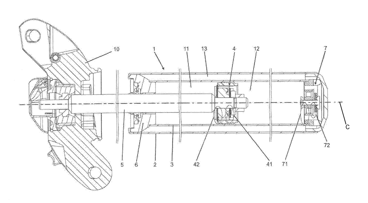
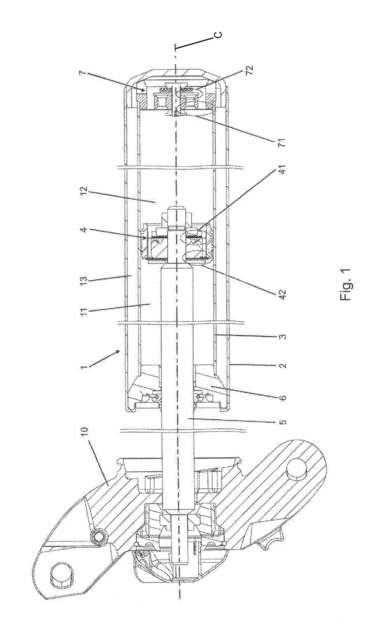
[0024]Referring to the Figures, wherein like numerals indicate corresponding parts throughout the several views, a twin-tube hydraulic damper assembly 1 is generally shown in FIG. 1.

[0025]The twin-tube hydraulic damper assembly 1, as generally shown in FIG. 1, may be employed in a typical motor vehicle suspension. The assembly 1 includes a main tube 3 disposed on a center axis C and defining a fluid chamber 11, 12 having an internal radius R2. The main tube 3 extends along the center axis C between a first end and a second end for containing a working liquid. A piston 4 is slidably disposed in the fluid chamber 11, 12 and movable along the center axis C. The piston 4 makes a sliding fit with the main tube 3 dividing the fluid chamber 11, 12 into a compression chamber 12 and a rebound chamber 11. The rebound chamber 11 extends between the first end of the main tube 3 and the piston 4. The compression chamber 12 extends between the second end of the main tube 3 and the piston 4. An ex...


PUM


Abstract

A twin-tube hydraulic damper assembly includes a main tube having an internal radius extending along a center axis between a first end and a second end. An external tube is disposed on the center axis extending about the main tube. A base valve attached to the second end for controlling the flow of the working liquid during the compression stroke and the rebound stroke. A rebound valve of at least one rebound deflective disc having a thickness is disposed in the compression chamber and adjacent to the body. The rebound deflective disc has an external circumferential surface spaced from the main tube defining an annular damping gap extending about the center axis and having a radial width whereby a ratio of said radial width of the annular damping gap to the internal radius is less than 10%.

Description

CROSS REFERENCE TO RELATED APPLICATION[0001]This application claims the benefit of provisional application Ser. No. 62 / 364,000 filed on Jul. 19, 2016, the contents of which are incorporated herein by reference in their entirety.BACKGROUND OF THE INVENTION1. Field of the Invention[0002]The present invention relates to a twin-tube hydraulic damper.2. Description of the Prior Art[0003]Prior art references disclose solutions providing improvements of acoustic performance of hydraulic dampers. For example, Patent publication DE102008042251 discloses a noise suppression unit arranged on the piston rod formed by a cylindrical sleeve with a diameter lower than diameter of the piston, arranged on the piston compression side. That construction provides annular inertial flow channel between the outer surface of the sleeve and the inner surface of the damper tube. That additional working liquid flow path provides noise suppression effect by means of the liquid inertial force.[0004]Patent public...

Claims


Application Information

Patent Timeline
IPC IPC(8): F16F9/34F16F9/348F16F9/32F16F9/06
CPCF16F9/341F16F9/3257F16F9/3485F16F9/067F16F9/185F16F9/3482F16F9/348
Inventor SIKORA, MARIANPALKA, WITOLD
Owner BEIJINGWEST INDUSTRIES
Why Eureka
Try Eureka