Decorative glass light and assembly method thereof

a technology of decorative glass and assembly method, which is applied in the direction of semiconductor devices for light sources, coupling device connections, lighting and heating apparatus, etc., can solve the problems of low luminous efficacy and waste of electricity, repetitive use of same structures, waste of materials, etc., and achieve low luminous efficacy, high luminous efficacy, and waste of electricity

Active Publication Date: 2018-05-10
MOON SANG PIL
View PDF0 Cites 1 Cited by
  • Summary
  • Abstract
  • Description
  • Claims
  • Application Information

AI Technical Summary

Benefits of technology

[0014]The beneficial effect brought by this invention is that the decorative glass light has high luminous efficacy and solves the disadvantage of low luminous efficacy and

Problems solved by technology

Existing decorative glass lights are conventional incandescent light bulbs with a base having an outer ring to fix glass, disadvantage of which is the low luminous efficacy and a waste of electricity.
Existing decor

Method used


Image

  • Decorative glass light and assembly method thereof
  • Decorative glass light and assembly method thereof
  • Decorative glass light and assembly method thereof

Examples


first embodiment

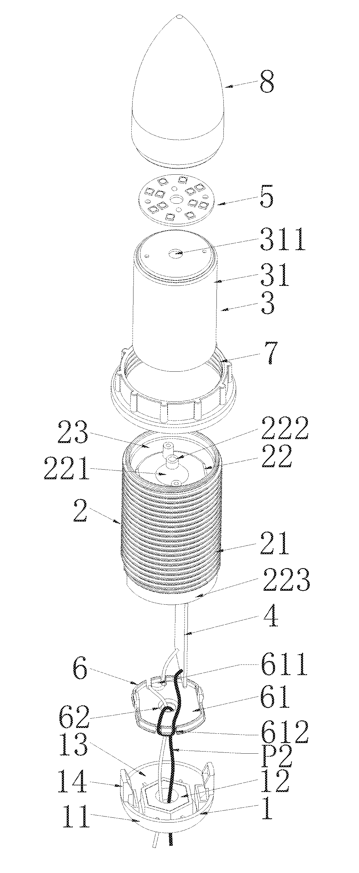
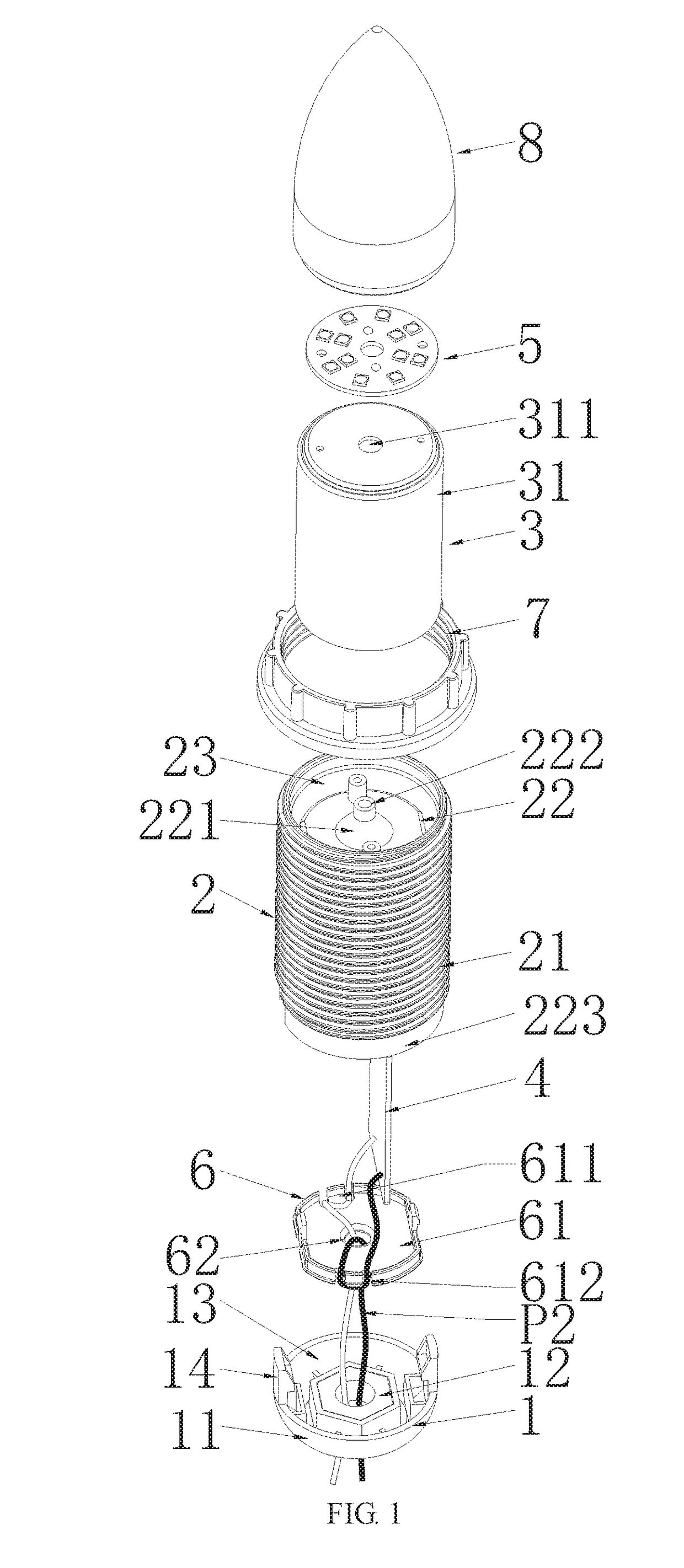
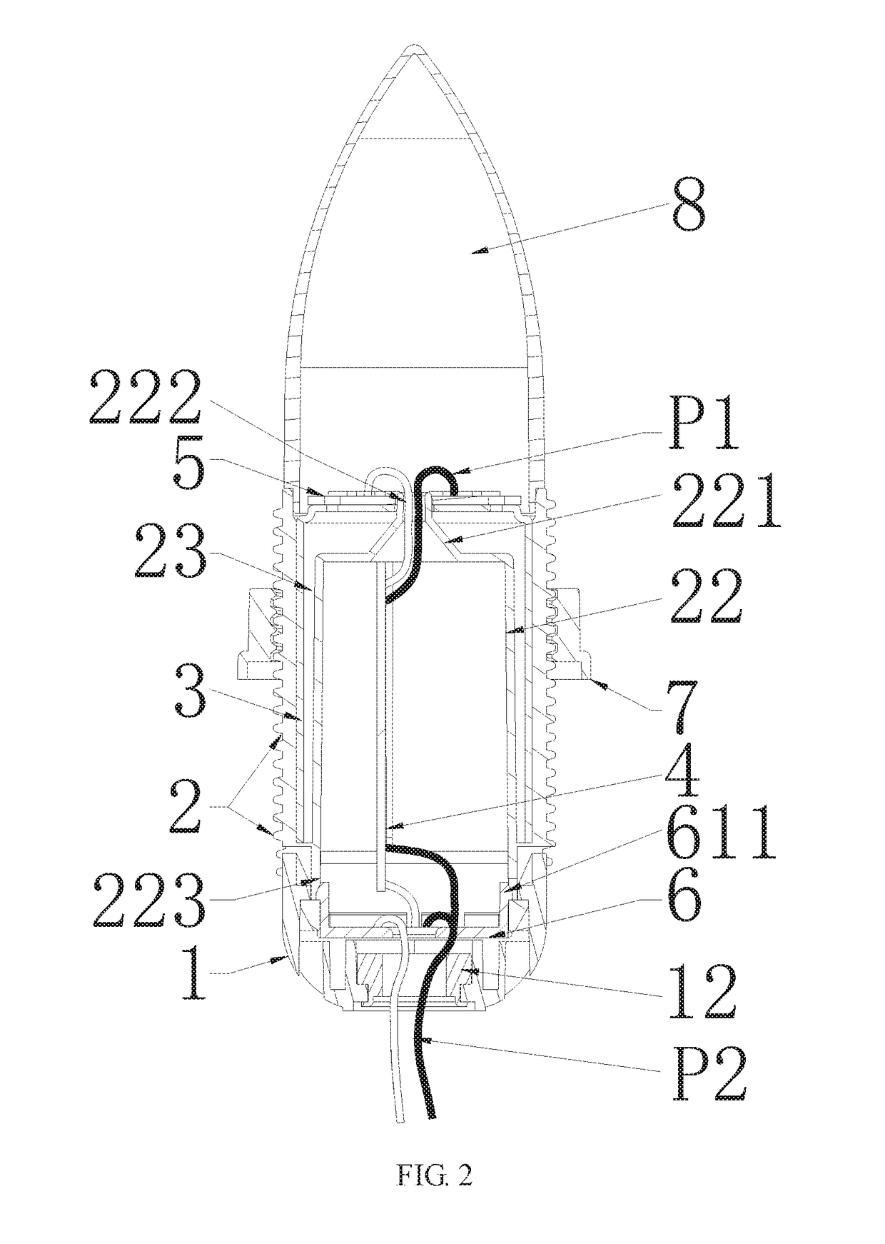
[0049]As shown in FIGS. 1 and 2 of the first embodiment, a decorative glass light of the present invention comprises a light base 1, a light body 2, a flange lock nut 7 threadedly connected to the light body 2 and a light shade 8. A heat-radiating tube 3 and a PCB (printed circuit board) 4 are sheathed in the light body 2. A LED board 5 is placed at a top of the light body 2. One end of the PCB 4 is connected to the LED board 5 through wires P1. Wires P2 connected to the other end of the PCB 4 passes through a PCB protection board 6. An interior screw thread of the flange lock nut 7 is screwed on an exterior screw thread of the light body 2.

[0050]In the present embodiment, the light body 2 consists of a tube-like body 21, an inner extension tube 22 that forms an annular gap 23 with the tube-like body 21 when it being sheathed concentrically in the tube-like body 21, a cone piece 221 that is concentrically projected from a top of the inner extension tube 22, a first wire hole 222 ope...

second embodiment

[0059]FIGS. 3 and 4 set out present invention.

[0060]As shown in FIGS. 3 and 4, the distinguishing feature of the second embodiment as compared with the first embodiment is the different structured light base. A light base 1 of the decorative glass light of the second embodiment consists of a second shallow bowl-like body 11 and tapped holes 15 that symmetrically stands on a junction portion of a side wall and a bottom of the second shallow bowl-like body 11.

[0061]Description of other same structures is omitted hereby.

[0062]As shown in FIGS. 3 and 4, the assembly method of the LED light bulb with soft light is set out as follows:

[0063]sheathing a heat-radiating tube 3 into an annular gap 23 formed within a light body 2, placing a LED board 5 on a top of the heat-radiating tube 3 using a screw, and sheathing a PCB 4 into an inner extension tube 22 from an opening 223 of the light body 2;

[0064]connecting the LED board 5 and the PCB 4 through wires P1, riveting wires P2 connected to the...


PUM


Abstract

The present invention relates to a decorative glass light having a light base, a light body and a light shade, wherein a heat-radiating tube and a PCB are sheathed in the light body, a LED board is placed at a top of the light body, one end of the PCB is connected to the LED board through wires, wires connected to the other end of the PCB pass through a PCB protection board.

Description

CROSS-REFERENCE TO RELATED APPLICATIONS[0001]The present application is a Continuation-in-part application of PCT application No. PCT / CN2016 / 073066 filed on Feb. 1, 2016, the contents of the above are hereby incorporated by reference.FIELD OF THE INVENTION[0002]The present invention relates to a pendant decorative light, especially to a decorative glass light and an assembly method thereof.BACKGROUND OF THE INVENTION[0003]Existing decorative glass lights are conventional incandescent light bulbs with a base having an outer ring to fix glass, disadvantage of which is the low luminous efficacy and a waste of electricity. Existing decorative glass lights may also be LED light bulbs having a LED driver and fixed on a conventional bulb base, disadvantage of which is the repetitive use of same structures, a waste of material and complicated assembly.SUMMARY OF THE INVENTION[0004]The present invention aims at providing a decorative glass light, a decorative glass light shade could be assem...

Claims


Application Information

Patent Timeline
IPC IPC(8): F21V29/70F21V17/06F21S2/00F21K9/235F21V17/12F21K9/232H01R33/09
CPCF21V29/70F21V17/06F21S2/00F21K9/235F21V17/12F21K9/232H01R33/09F21Y2115/10F21V29/506F21V23/006F21Y2105/18
Inventor MOON, DAI SUNGMOON, SANG PIL
Owner MOON SANG PIL
Why Eureka
Try Eureka