Unlock instant, AI-driven research and patent intelligence for your innovation.
Light-Emitting Element, Light-Emitting Device, Electronic Device, and Lighting Device
Active Publication Date: 2018-05-31
SEMICON ENERGY LAB CO LTD
View PDF1 Cites 27 Cited by
Summary
Abstract
Description
Claims
Application Information
AI Technical Summary
This helps you quickly interpret patents by identifying the three key elements:
Problems solved by technology
Method used
Benefits of technology
Benefits of technology
This patent describes a new light-emitting element that has high reliability and can maintain good characteristics over a long period of driving. It also has high color purity and efficiency, as well as low power consumption and a long lifetime when used in a light-emitting device. Additionally, it can be used in electronic devices and lighting devices that have a long lifetime and low power consumption. This new technology achieves these improvements through a unique structure of the light-emitting layer that allows for compensation for changes in carrier balance and maintains a stable state over time.
Problems solved by technology
Even if the characteristics of the light-emitting element in the initial stage are favorable, in the case where the light-emitting element cannot withstand long-time driving and the lifetime as an element is short, the utility value is low and the commercialization is difficult.
Method used
Image
Click on the blue label to locate the original text in one second.
Reading with bidirectional positioning of images and text.
Examples
embodiment 1
[0075]In this embodiment, a light-emitting element of one embodiment of the present invention is described.
[0076]The light-emitting element of one embodiment of the present invention is formed in a manner that an EL layer including a light-emitting layer is sandwiched between a pair of electrodes, and the EL layer has a stacked-layer structure of at least a first light-emitting layer, a second light-emitting layer, and a third light-emitting layer.
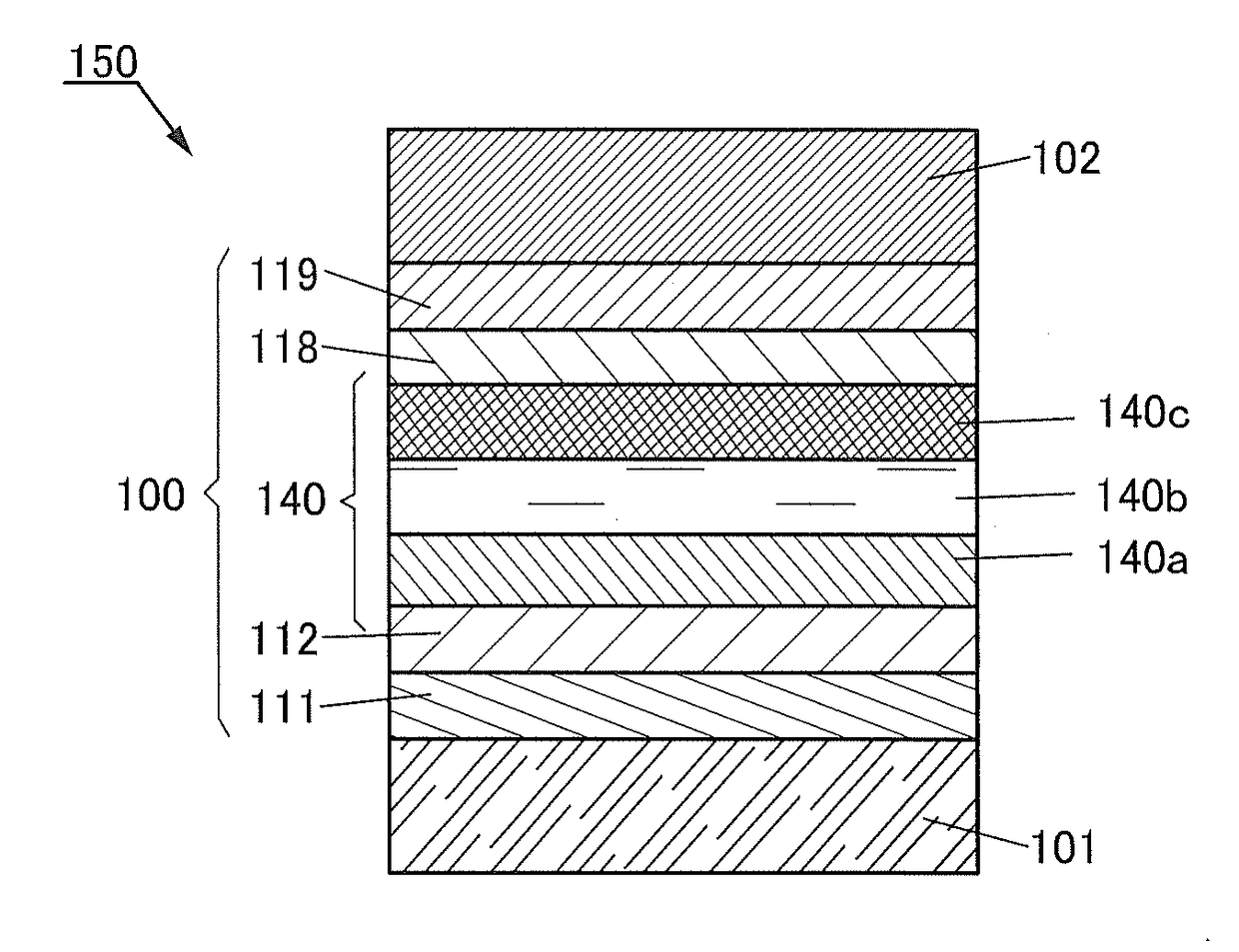
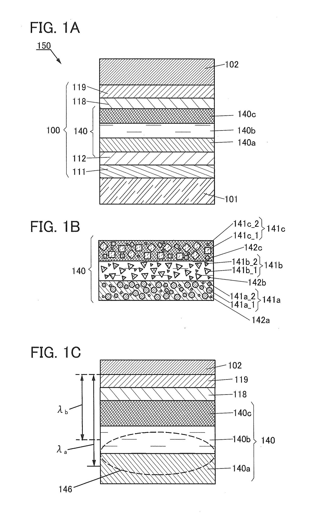
[0077]An element structure of the light-emitting element of one embodiment of the present invention is described below with reference to FIGS. 1A to 1C.
[0078]In a light-emitting element 150 illustrated in FIG. 1A, an EL layer 100 that includes a light-emitting layer 140 is provided between a pair of electrodes (an electrode 101 and an electrode 102). The EL layer 100 has a structure in which a hole-injection layer 111, a hole-transport layer 112, a light-emitting layer 140 (140a, 140b, and 140c), an electron-transport layer 118, an electro...
embodiment 2
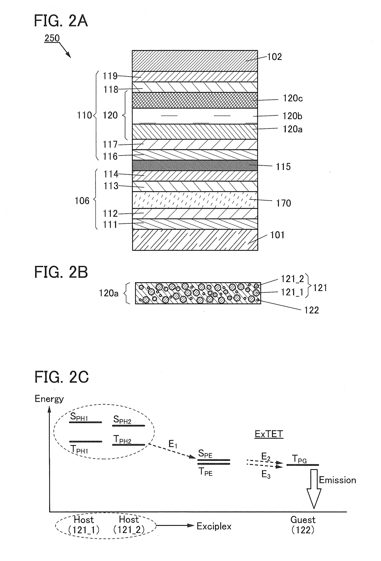
[0177]In this embodiment, a light-emitting element having a structure different from that described in Embodiment 1 and light emission mechanisms of the light-emitting elements will be described below with reference to FIGS. 2A to 2C. In FIGS. 2A and 2B, a portion having a function similar to that in FIGS. 1A to 1C is represented by the same hatch pattern as in FIGS. 1A to 1C and not especially denoted by a reference numeral in some cases. In addition, common reference numerals are used for portions having similar functions, and a detailed description of the portions is omitted in some cases.
Structure Example of Light-Emitting Element
[0178]FIG. 2A is a schematic cross-sectional view of a light-emitting element 250.
[0179]The light-emitting element 250 illustrated in FIG. 2A includes a plurality of light-emitting units (a light-emitting unit 106 and a light-emitting unit 110) between a pair of electrodes (the electrode 101 and the electrode 102). One of the light-emitting units prefer...
embodiment 3
[0216]In this embodiment, examples of a light-emitting device of one embodiment of the present invention are described with reference to FIGS. 3A and 3B and FIGS. 4A and 4B.
Structure Example 1 of Light-Emitting Device
[0217]FIGS. 3A and 3B are cross-sectional views each illustrating a light-emitting element of one embodiment of the present invention. In FIGS. 3A and 3B, a portion having a function similar to that in FIG. 1A is represented by the same hatch pattern as in FIG. 1A and not especially denoted by a reference numeral in some cases. In addition, common reference numerals are used for portions having similar functions, and a detailed description of the portions is omitted in some cases.
[0218]Light-emitting elements 260a and 260b in FIGS. 3A and 3B may have a bottom-emission structure in which light is extracted through the substrate 200 or may have a top-emission structure in which light is extracted in the direction opposite to the substrate 200. However, one embodiment of t...
PUM
Abstract
A highly reliable light-emitting element which can keep favorable characteristics throughout long-time driving is provided. In addition, a light-emitting element with high color purity and high emission efficiency is provided. Furthermore, a light-emitting device having a long lifetime in which the light-emitting element is used is provided. Moreover, an electronic device and a lighting device each of which has a long lifetime are provided. In the light-emitting element including an EL layer between a pair of electrodes, the EL layer has a stacked-layer structure of a first light-emitting layer, a second light-emitting layer, and a third light-emitting layer. The light-emitting layer includes an electron-transport material, a hole-transport material, and a light-emitting material. Furthermore, light emitted from the first light-emitting layer and light emitted from the third light-emitting layer have the same color and each have a longer wavelength than light emitted from the second light-emitting layer.
Description
TECHNICAL FIELD[0001]One embodiment of the present invention relates to a novel light-emitting element. One embodiment of the present invention also relates to a light-emitting device, an electronic device, and a lighting device each including the light-emitting element.[0002]Note that one embodiment of the present invention is not limited to the above technical field. The technical field of one embodiment of the invention disclosed in this specification and the like relates to an object, a method, or a manufacturing method. In addition, one embodiment of the present invention relates to a process, a machine, manufacture, or a composition of matter. Specifically, examples of the technical field of one embodiment of the present invention disclosed in this specification include a semiconductor device, a light-emitting device, a display device, a lighting device, a power storage device, a memory device, a method for driving any of them, and a method for manufacturing any of them.BACKGR...
Claims
Application Information
Patent Timeline
Application Date:The date an application was filed.
Publication Date:The date a patent or application was officially published.
First Publication Date:The earliest publication date of a patent with the same application number.
Issue Date:Publication date of the patent grant document.
PCT Entry Date:The Entry date of PCT National Phase.
Estimated Expiry Date:The statutory expiry date of a patent right according to the Patent Law, and it is the longest term of protection that the patent right can achieve without the termination of the patent right due to other reasons(Term extension factor has been taken into account ).
Invalid Date:Actual expiry date is based on effective date or publication date of legal transaction data of invalid patent.

