Brushless Motor

a brushless motor and motor body technology, applied in the direction of dynamo-electric machines, electrical equipment, magnetic circuit shapes/forms/construction, etc., can solve the problem of inferior reading precision of position detection, and achieve the effect of limiting the magnetic influence of drive magnets and highly reliable position detection signals

Inactive Publication Date: 2018-07-19
TOKYO PARTS IND CO LTD
View PDF0 Cites 3 Cited by
  • Summary
  • Abstract
  • Description
  • Claims
  • Application Information

AI Technical Summary

Benefits of technology

[0008]One or more exemplary mode of embodiment of the present invention provides a brushless motor capable of substantially limiting the magnetic influence of a drive magnet and obtaining a highly reliable position detection signal.

Problems solved by technology

H05-191939, there is a problem that, because the position detection magnets are directly fixed to the drive magnets, the position detection magnet is subjected to considerable magnetic influence by the drive magnet, and thus the reading precision in position detection is inferior.

Method used


Image

  • Brushless Motor
  • Brushless Motor
  • Brushless Motor

Examples


embodiment

Third Exemplary Mode of Embodiment

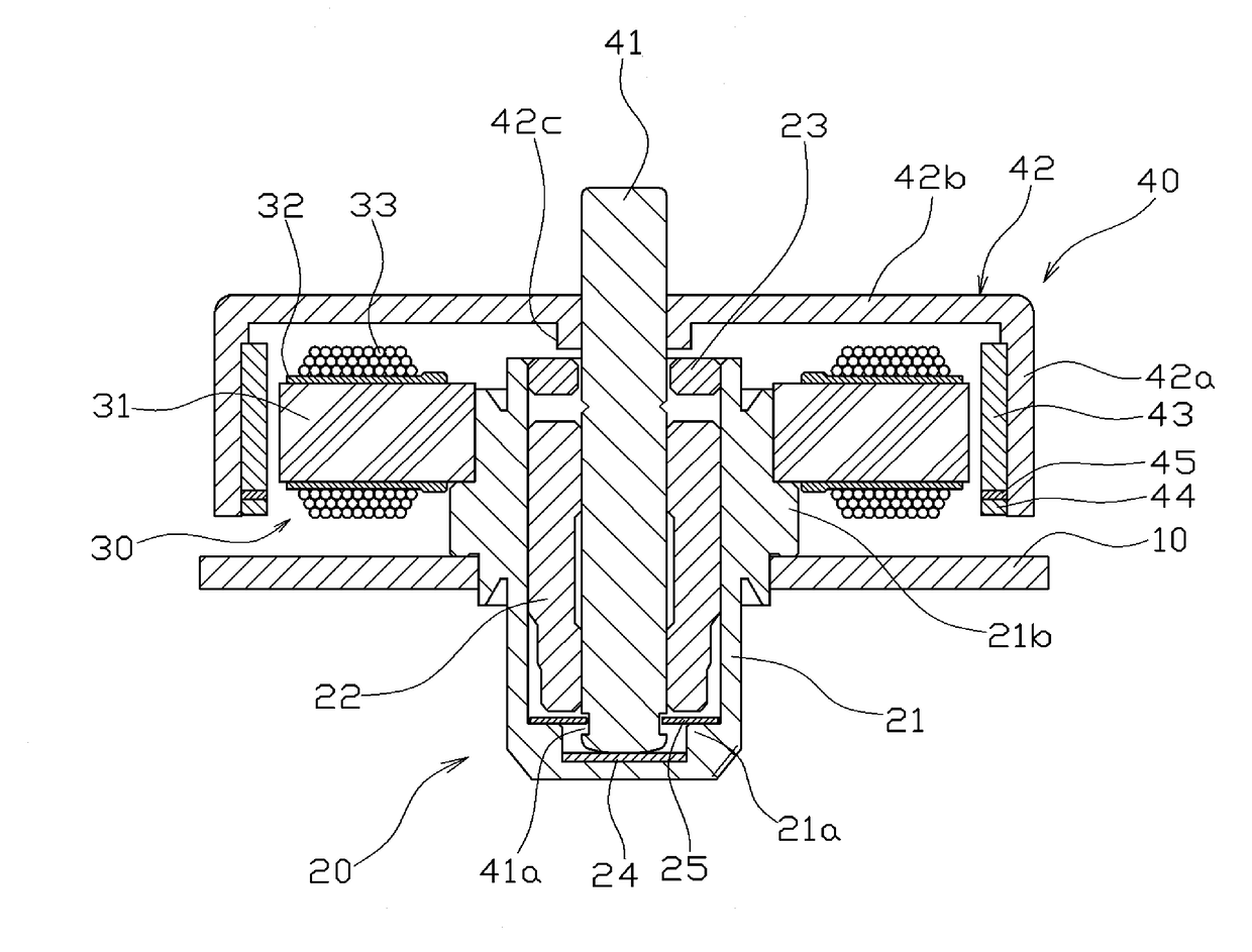
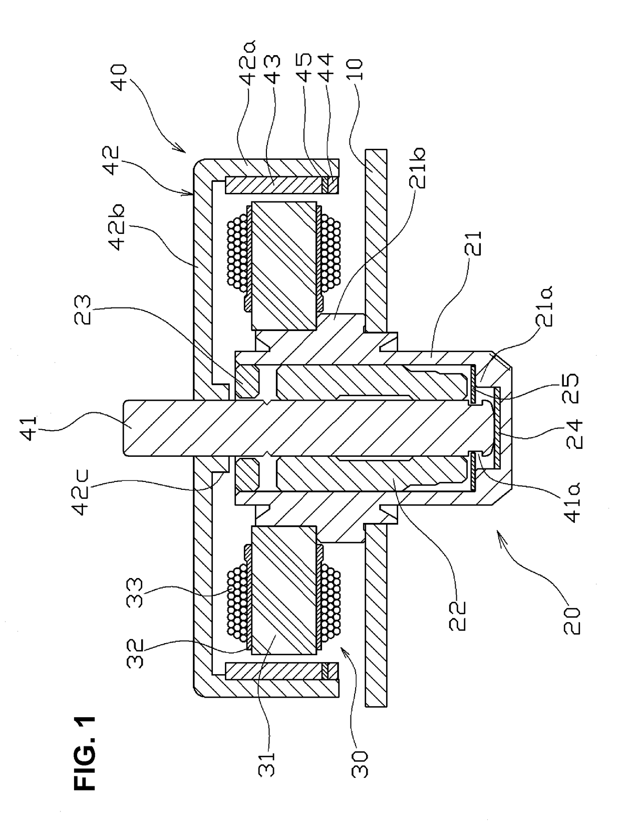
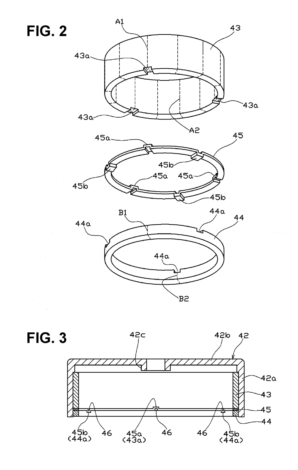
[0071]A third exemplary mode of embodiment of the present invention will be described with reference to FIG. 6 and FIG. 7. In this example, only the configurations of the position detection magnet 44 and the separation plate 45 are different from the first exemplary mode of embodiment.

[0072]At the top end face of the position detection magnet 44, rectangular recesses 44a with identical shapes are provided at a pitch of 120° in the circumferential direction. The center, in the circumferential direction, of one of these three recesses 44a is located in the boundary region B1 between the magnetic poles of the position detection magnet 44.

[0073]The separation plate 45 of this example is made from an integrally molded heat-resistant resin part. Protrusions 45a with identical shapes are provided on the top face of the separation plate 45, at a pitch of 120° in the circumferential direction. These protrusions 45a have a shape corresponding to the recesses ...


PUM


Abstract

In a brushless motor having a rotor in which a drive magnet 43 and a position detection magnet 44 are fixed to the inside of a rotor case 44, along the axial direction, an annular separation plate 45 having positioning parts 45a and 45b for positioning these in the circumferential direction is disposed between the drive magnet 43 and the position detection magnet 44. Thereby, the magnetic influence of the drive magnet can be limited, and thus a highly reliable position detection signal can be obtained.

Description

BACKGROUND1. Technical Field[0001]The present invention relates to a brushless motor having a position detection mechanism.2. Related Art[0002]Brushless motors of the so-called outer rotor type, which have an outer rotor, are used as spindle motors for rotationally driving color wheels in projector devices, polygon mirrors in printer devices and the like. Brushless motors of this sort are known in which with a magnet is provided for detecting the speed of the rotor, or a mechanism is provided that outputs an index signal having one pulse for each revolution of the rotor so as to detect the rotational position of the rotor.[0003]For example, Japanese Patent Laid-Open Publication No. 2006-314165 describes a motor in which the drive magnet protrudes beyond the bottom face of a rotor holder and a position detection magnet is mounted on the outer circumferential face of the protrusion concentric with the rotor holder.[0004]With the motor described in Japanese Patent Laid-Open Publication...

Claims


Application Information

Patent Timeline
Patent Type & Authority Applications(United States)
IPC IPC(8): H02K11/21H02K1/12
CPCH02K11/21H02K1/12H02K21/22H02K29/08H02K11/215
Inventor NISHIDATE, MASAHIRO
Owner TOKYO PARTS IND CO LTD
Why Eureka
Try Eureka