Rotation angle detection device

a detection device and rotation angle technology, applied in the direction of mechanical control devices, process and machine control, instruments, etc., can solve the problems of deterioration of the operation performance of the accelerator pedal b>3/b>, easy wear and tear of the resin-made rotation-sliding portion, and unsatisfactory strength and heat resistance. , to achieve the effect of reducing the deterioration of the detection accuracy of the rotation angle, reducing the cost and strengthening the magneti

Inactive Publication Date: 2007-05-10
DENSO CORP
View PDF7 Cites 32 Cited by
  • Summary
  • Abstract
  • Description
  • Claims
  • Application Information

AI Technical Summary

Benefits of technology

[0014] Moreover, the detection object is fixedly mounted at the yoke, without being fixedly mounted at a shaft as disclosed in the prior art. Thus, it is capable to restrict the deterioration of a detection accuracy of the rotation angle due to a deviation of the attachment position of the yoke with respect to the shaft.
[0015] Because the magnetism generation unit (e.g., permanent magnet) is fixed to the inner surface of the yoke to generate the magnetic flux at the inner side of the yoke, it becomes unnecessary to provide a special shape for the permanent magnet. Thus, the cost can be reduced. Moreover, the yoke is constructed of the magnetic metal, to construct a part of a magnetic path of the magnetic flux from the permanent magnet. Thus, the magnetic force of the permanent magnet can be strengthened. Because the yoke can function as a magnetic shield, the influence of the magnetic flux from the exterior on the magnetism detection member can be restricted.

Problems solved by technology

Therefore, in the case where the accelerator pedal 3 made of the resin is supported by the bearing J made of the resin, the strength, the heat resistance and the durability to withstand the operation of the accelerator pedal device are unsatisfactory.
Therefore, the wearing away at the resin-made rotation-sliding portion readily occurs during the long term use.
Thus, the operation performance of the accelerator pedal 3 will be deteriorated.
As a result, the magnetic flux applied to the magnetism detection member 8 is varied, thus deteriorating the detection accuracy of the rotation angle.

Method used


Image

  • Rotation angle detection device
  • Rotation angle detection device
  • Rotation angle detection device

Examples


embodiment

Preferred Embodiment

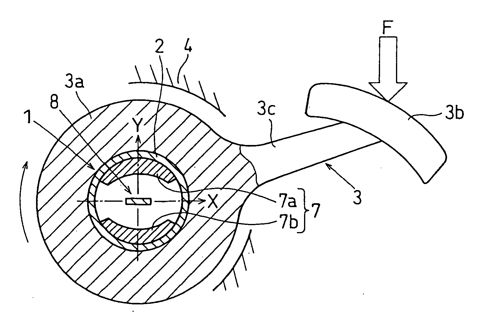
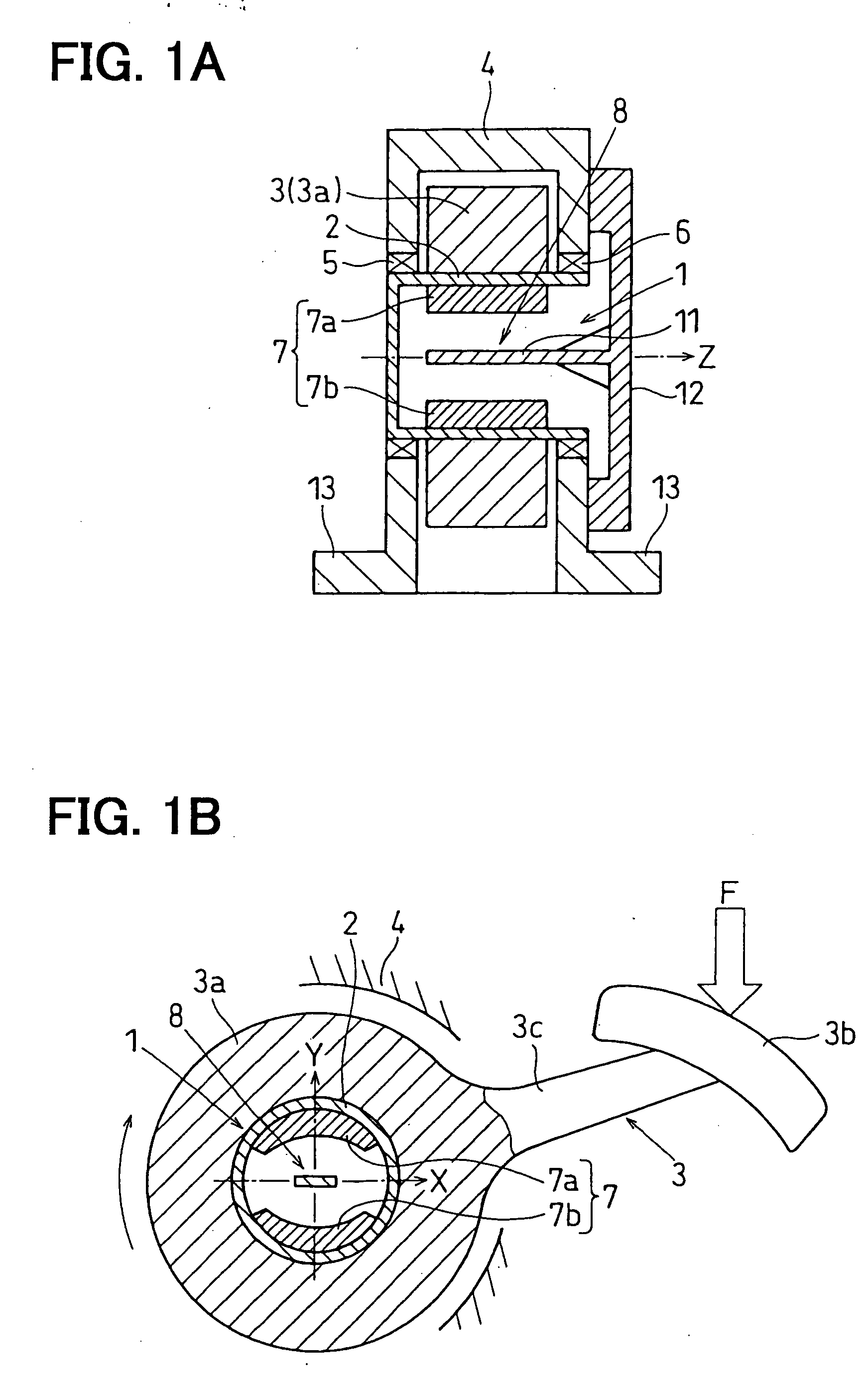
[0026] A rotation angle detection device for detecting a rotation angle of an object according to a preferred embodiment of the present invention will be described with reference to FIGS. 1A-3. For example, the rotation angle detection device can be suitably used as an accelerator pedal device for detecting a rotation angle of an accelerator pedal 3, which is rotatably supported and operated by a passenger foot or the like.

[0027] As shown in FIGS. 1A and 1B, the accelerator pedal device has a rotation detection sensor 1 (of noncontact type, for example), the accelerator pedal 3, a housing 4 (i.e., support member), a first bearing 5, a second bearing 6, and a return spring (not shown). The rotation detection sensor 1 includes a yoke 2, a magnetism detection member 8, and a magnetism generation unit 7 (e.g., permanent magnet) which can be constructed of a magnetic-flux generating portion 7a and a magnetic-flux attracting portion 7b.

[0028] The yoke 2 can be made o...


PUM


Abstract

A rotation angle detection device for detecting a rotation angle of an object has a substantially cylinder-shaped yoke, a magnetism generation unit which is fixed to an inner surface of the yoke, a magnetism detection member which is arranged substantially in a center axis of the yoke, at least one bearing which rotatably supports the yoke, and a support member which holds the bearing. The yoke is made of a magnetic metal, and fixedly mounted at the object to be rotatable integrally with the object. The magnetism generation unit generates a magnetic field substantially perpendicular to the center axis of the yoke. The magnetism detection member generates an output corresponding to a variation of the magnetic field to detect the rotation angle of the object relative to the magnetism detection member.

Description

CROSS REFERENCE TO RELATED APPLICATION [0001] This application is based on a Japanese Patent Application No. 2005-326517 filed on Nov. 10, 2005, the disclosure of which is incorporated herein by reference. FIELD OF THE INVENTION [0002] The present invention relates to a rotation angle detection device, which can be suitably used to contactlessly detect a rotation angle of an object. BACKGROUND OF THE INVENTION [0003] Generally, a rotation angle detection device (e.g., accelerator pedal device) is provided with a rotation detection sensor which contactlessly detects a rotation angle of a detection object (e.g., accelerator pedal) rotatably supported by a support member. The rotation detection sensor has a permanent magnet for generating a parallel magnetic field, and a magnetism detection member which is fixed in the parallel magnetic field of the permanent magnet to generate output corresponding to magnetic lines of force. [0004] As disclosed in U.S. 2002 / 0175676A1, referring to FIG...

Claims


Application Information

Patent Timeline
Patent Type & Authority Applications(United States)
IPC IPC(8): G01B7/30
CPCG01D5/145G05G1/38G01D2205/40
Inventor HORIE, KAZUYUKIHARIU, TETSUOKOBAYASHI, YASUNORIKANO, MASAO
Owner DENSO CORP
Why Eureka
Try Eureka