Self-compensating dynamic balancer

Inactive Publication Date: 2001-04-10
SAMSUNG ELECTRONICS CO LTD
View PDF11 Cites 17 Cited by
  • Summary
  • Abstract
  • Description
  • Claims
  • Application Information

AI Technical Summary

Benefits of technology

It is an object of the present invention to provide an improved self-compensa

Problems solved by technology

In a typical rotating body, the center of rotation and the center of gravity of the rotating body, do not match due to eccentric mass caused by a

Method used


Image

  • Self-compensating dynamic balancer
  • Self-compensating dynamic balancer
  • Self-compensating dynamic balancer

Examples


Example

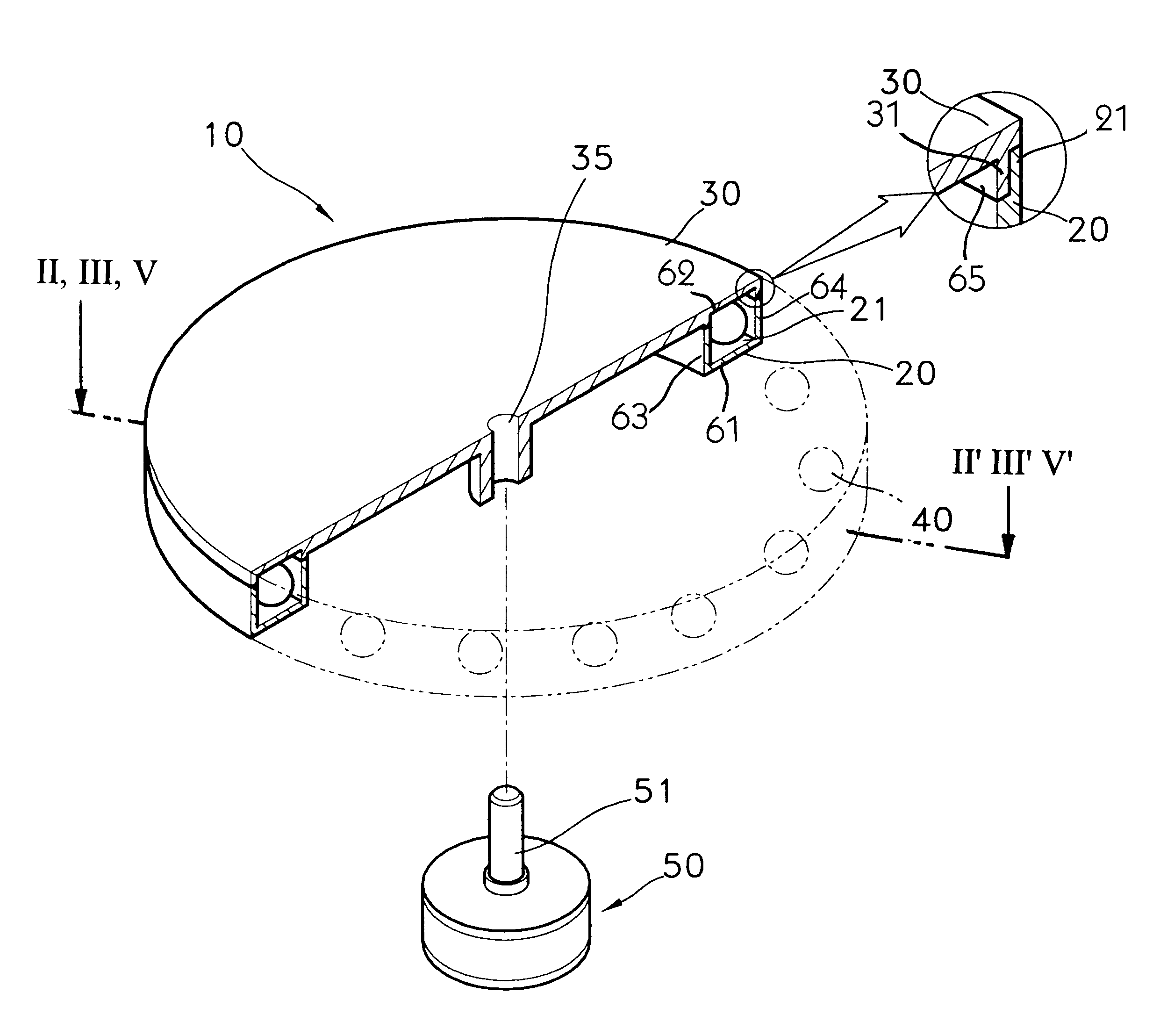
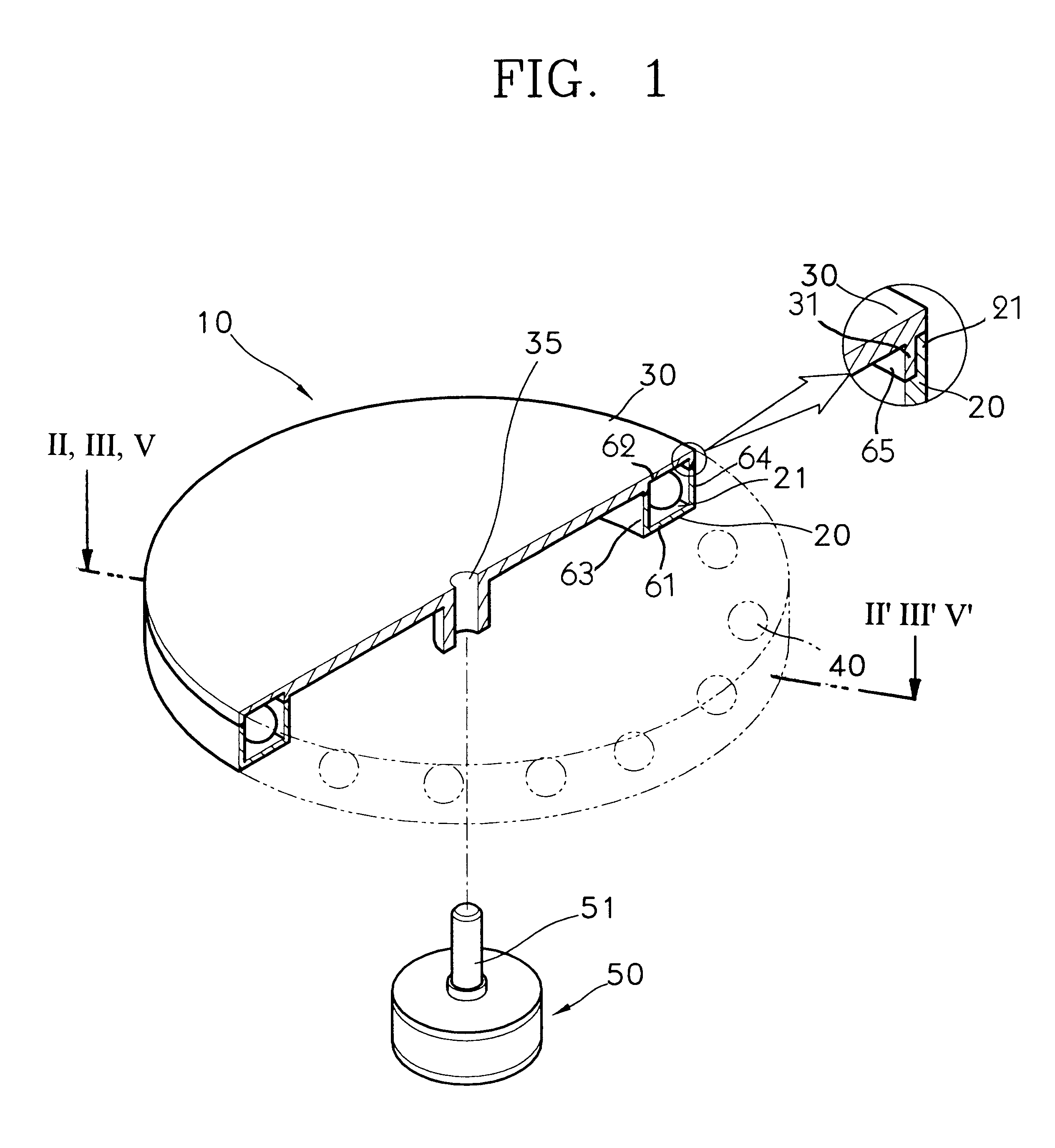
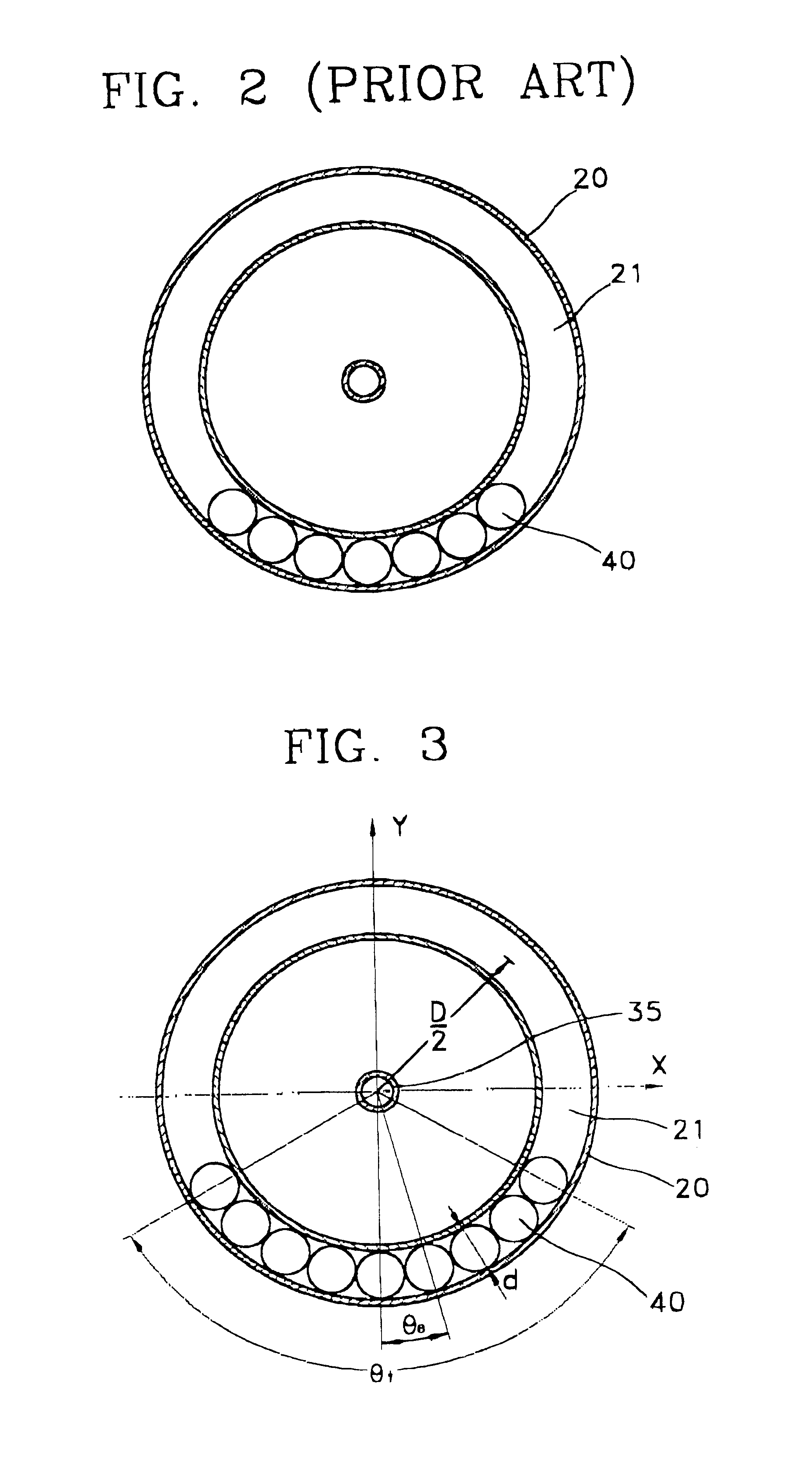
Referring to FIG. 2, typical dynamic balancer includes a housing 2, a race 3 formed on the housing 2, and rigid bodies 4 moving within race 3. FIG. 1 shows a self-compensating dynamic balancer for having a rotation body and a driving source rotating the rotation body reducing internal vibrations. The rotation body includes a case 10 and a plurality of rigid bodies 40 in the case 10. The case 10 consists of a main body 20 having an opening at the upper side thereof and a cover member 30 for covering the opening of the main body 20. The main body 20 has a hollow circular race 21 which is formed therein for accommodating the rigid bodies 40. The hollow circular race 21 defines an inner side 63, an outer side 64, and upper side 62, and a lower side 61. A first circumferential side 31 extended from cover member 30 and a second circumferential side 21 extended from main body 20 from the outer side 64. Each end portion of first and second circumferential sides 21 and 31 overlaps each other...


PUM


Abstract

In a self-compensating dynamic balancer, a main body is installed at a rotating body to restrict internal vibrations due to eccentric mass of the rotating body. The main body has a circular race formed therein around a rotation shaft of the rotating body. A plurality of rigid bodies are disposed in the race to be capable of moving freely and are as many as necessary to occupy at least half of the inner space of the race.

Description

BACKGROUND OF THE INVENTIONField of the InventionThe present invention relates to a self-compensating dynamic balancer, and more particularly, to a process and a self-compensating dynamic balancer providing an improved structure to reduce the effect of a frictional force.Description of the Related ArtIn a typical rotating body, the center of rotation and the center of gravity of the rotating body, do not match due to eccentric mass caused by an error during the manufacturing process. I have noticed that when the rotating body having a center of rotation which does not match the center of gravity rotates, the center of rotation revolves, i.e., whirls. As a result, internal vibrations are generated in the rotating body, particularly in a radial direction.SUMMARY OF THE INVENTIONIt is an object of the present invention to provide an improved self-compensating balancer and process for self-compensated balancing of rotating devices.It is another object to provide a self-compensating dyna...

Claims


Application Information

Patent Timeline
IPC IPC(8): F16F15/00F16F15/36G11B33/08
CPCF16F15/363G11B33/08Y10T74/2111
Inventor SOHN, JIN-SEUNG
Owner SAMSUNG ELECTRONICS CO LTD
Why Eureka
Try Eureka