[0007]Upon failure of the continued
combustion condition of continuing combustion in the internal combustion engine, the power output apparatus according to this aspect of the invention sets the target operating condition of the internal combustion engine including the intermittent operation of the internal combustion engine based on the driving force demand that is to be output to the driveshaft. Upon satisfaction of the continued combustion condition, on the other hand, the power output apparatus continues operation of the internal combustion engine and sets the target operating condition of the internal combustion engine based on the driving force demand. In the state other than the specific driving state of applying a braking force or a small load to the driveshaft upon satisfaction of the continued combustion condition, the power output apparatus performs the continued medium-
high load combustion control which controls the internal combustion engine, the
electric power-mechanical power
input output structure, and the motor to drive the internal combustion engine in the set target operating condition and to ensure output of a driving force equivalent to the driving force demand to the driveshaft. Such control ensures output of a driving force equivalent to the driving force demand to the driveshaft, while driving the internal combustion engine in the set target operating condition with intermittent operation of the internal combustion engine. In the specific driving state, on the other hand, the power output apparatus performs the continued
low load combustion control which controls the internal combustion engine, the
electric power-mechanical power
input output structure, and the motor to drive the internal combustion engine in the set target operating condition with continued combustion in the internal combustion engine and to ensure output of a driving force equivalent to the set driving force demand to the driveshaft. Such control enables the internal combustion engine to be driven in the target operating condition with continued combustion, while ensuring output of the driving force equivalent to the braking force demand to the driveshaft. When the target operating condition of the internal combustion engine upon satisfaction of the continued combustion condition is an operating condition of a relatively low rotation speed, the power output apparatus enables the internal combustion engine to be driven in the target operating condition of the relatively low rotation speed with continued combustion. This arrangement effectively reduces the wasteful fuel consumption and thereby enhances the overall energy efficiency of the power output apparatus.
[0010]In one preferable embodiment according to this aspect of the invention, the power output apparatus further has an input
limit setting module that sets an input limit of the accumulator unit as a maximum
power level of allowing charge of the accumulator unit, based on a state of the accumulator unit. In this embodiment, the control module controls the internal combustion engine, the
electric power-mechanical power
input output structure, and the motor in a range of the set input limit of the accumulator unit. This arrangement effectively prevents the accumulator unit from being overcharged with excess electric power. The power output apparatus of this embodiment preferably has a charge-
discharge electric
power detector that measures a charge-
discharge electric power of charging the accumulator unit or being discharged from the accumulator unit. When execution of the continued
low load combustion control to limit the measured charge-
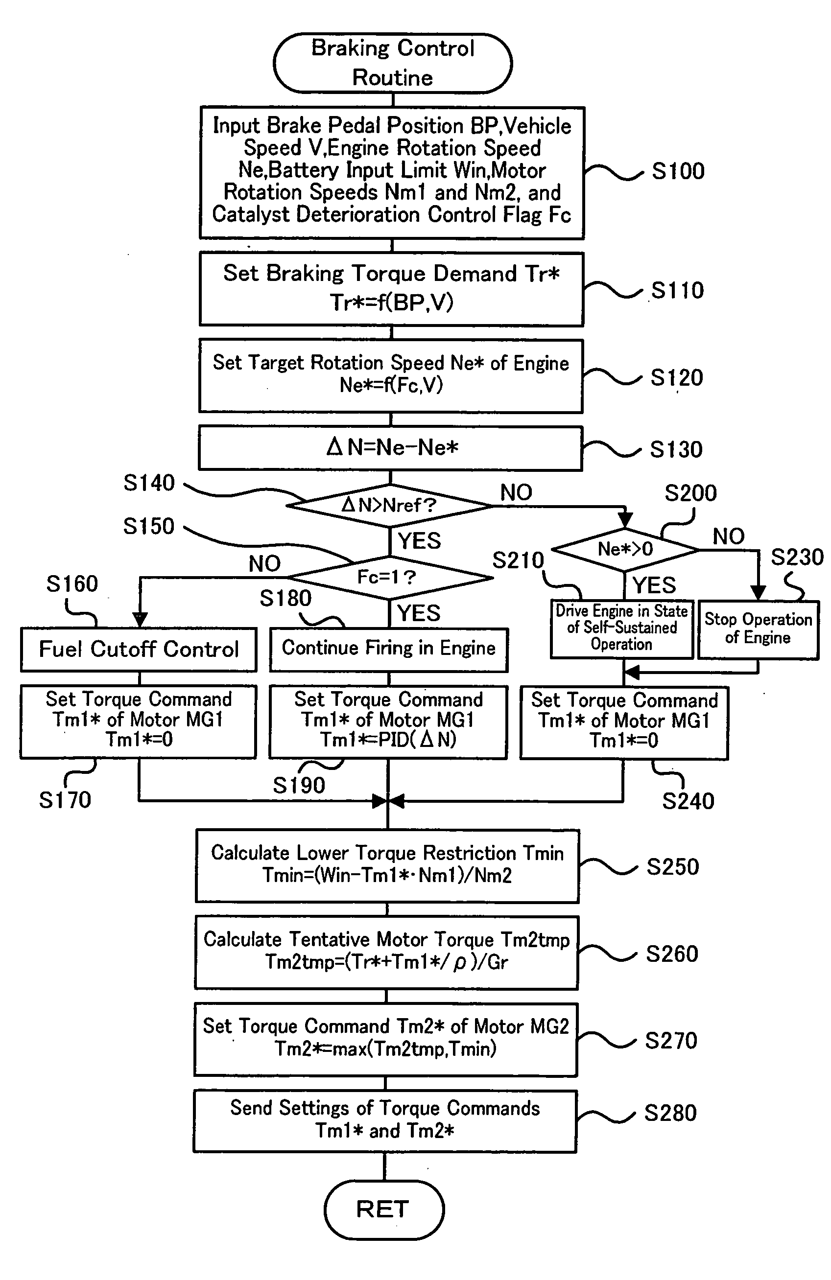
discharge electric power in the range of the set input limit of the accumulator unit in the specific driving state makes it impossible to drive the internal combustion engine in the set target operating condition, the control module performs fuel cutoff control of stopping
fuel injection in the internal combustion engine to enable the internal combustion engine to be driven in the target operating condition. This arrangement ensures the operation of the internal combustion engine in the target operating condition. In one preferable example of this embodiment, the control module controls the internal combustion engine, the electric power-mechanical power input output structure, and the motor to change a rotation speed of the internal combustion engine by a preset rotation speed per unit time in the course of the fuel cutoff control of stopping
fuel injection in the internal combustion engine to enable the internal combustion engine to be driven in the target operating condition. This arrangement effectively prevents an abrupt change of the rotation speed of the internal combustion engine and avoids potential troubles caused by the abrupt change of the rotation speed of the internal combustion engine, for example, a potential torque shock.
[0014]The vehicle according to this aspect of the invention is equipped with the power output apparatus having any of the above arrangements and thus exerts the similar effects to those of the power output apparatus described above. Namely the vehicle ensures output of a driving force equivalent to the driving force demand to the driveshaft, while driving the internal combustion engine in the set target operating condition with the intermittent operation of the internal combustion engine. The vehicle also enables the internal combustion engine to be driven in the target operating condition with continued combustion, while ensuring output of a driving force equivalent to the braking force demand to the driveshaft. The vehicle enables the internal combustion engine to be driven in the target operating condition of the relatively low rotation speed with continued combustion. This arrangement effectively reduces the wasteful fuel consumption and thereby enhances the overall energy efficiency of the power output apparatus.
[0016]Upon failure of the continued combustion condition of continuing combustion in the internal combustion engine, the control method of the power output apparatus according to this aspect of the invention sets the target operating condition of the internal combustion engine including the intermittent operation of the internal combustion engine based on the driving force demand that is to be output to the driveshaft. Upon satisfaction of the continued combustion condition, on the other hand, the control method of the power output apparatus continues operation of the internal combustion engine and sets the target operating condition of the internal combustion engine based on the driving force demand. In the state other than the specific driving state of applying a braking force or a small load to the driveshaft upon satisfaction of the continued combustion condition, the control method of the power output apparatus performs the continued medium-
high load combustion control which controls the internal combustion engine, the electric power-mechanical power input output structure, and the motor to drive the internal combustion engine in the set target operating condition and to ensure output of a driving force equivalent to the driving force demand to the driveshaft. Such control ensures output of a driving force equivalent to the driving force demand to the driveshaft, while driving the internal combustion engine in the set target operating condition with intermittent operation of the internal combustion engine. In the specific driving state, on the other hand, the control method of the power output apparatus performs the continued
low load combustion control which controls the internal combustion engine, the electric power-mechanical power input output structure, and the motor to drive the internal combustion engine in the set target operating condition: with continued combustion in the internal combustion engine and to ensure output of a driving force equivalent to the set driving force demand to the driveshaft. Such control enables the internal combustion engine to be driven in the target operating condition with continued combustion, while ensuring output of the driving force equivalent to the braking force demand to the driveshaft. When the target operating condition of the internal combustion engine upon satisfaction of the continued combustion condition is an operating condition of a relatively low rotation speed, the control method of the power output apparatus enables the internal combustion engine to be driven in the target operating condition of the relatively low rotation speed with continued combustion. This arrangement effectively reduces the wasteful fuel consumption and thereby enhances the overall energy efficiency of the power output apparatus.

