Fuel cell system and method of controlling same

Active Publication Date: 2005-09-08
HONDA MOTOR CO LTD
View PDF1 Cites 2 Cited by
  • Summary
  • Abstract
  • Description
  • Claims
  • Application Information

AI Technical Summary

Benefits of technology

[0010] The fuel cell system described above is able to provide protection against a malfunction that the system does not proceed to starting of power generation when the output voltage increases slowly. Furt

Problems solved by technology

However, the technique disclosed in the patent document, which introduces power generation by closing the hydrogen discharge valve when the output voltage of the fuel cell has reached the threshold, has a drawback that it is difficult to implement stable power generation.
This drawback is ascribed to the fact that a fuel cell, whose rate of voltage rise is higher for example, probably has a large amount of impurities in a hydrogen gas passage when an output voltage of the fuel cell has reached a threshold in spite of insufficient discharging with a hydrogen gas.
Namely, because the unconsumed impurities remain at a hydrogen electrode, it is difficult

Method used


Image

  • Fuel cell system and method of controlling same
  • Fuel cell system and method of controlling same
  • Fuel cell system and method of controlling same

Examples


Example

[0014] An embodiment of the present invention is now described with reference to the accompanying drawings.

[0015] Though description is given of a fuel cell system which is mounted on a vehicle (not shown) as an example, it goes without saying that it is possible to adopt other types of application.

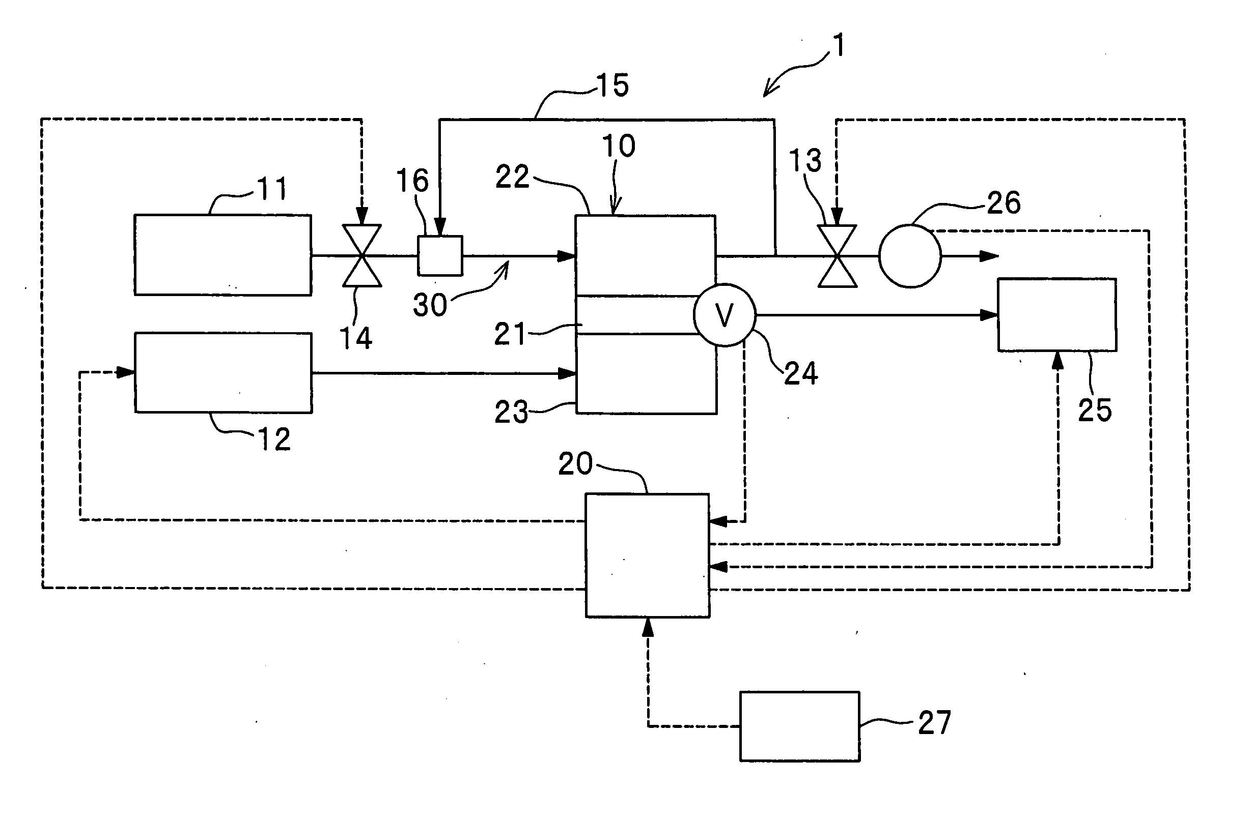
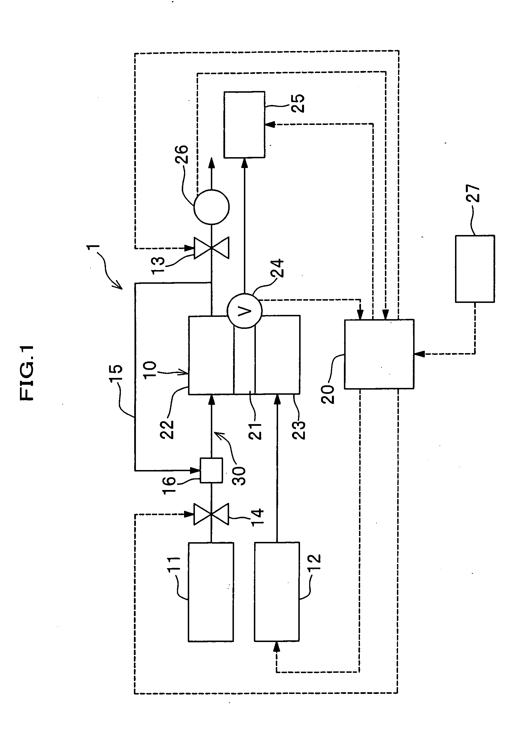
[0016] A fuel cell system 1 includes a fuel cell 10, a hydrogen supply device (fuel supply device) 11 and a discharge valve (gas discharge valve) 13. The fuel cell 10 is connected with a passage 30 for supplying a hydrogen gas. The hydrogen supply device 11 is disposed upstream and the discharge valve 13 downstream each relative to the fuel cell 10. The discharge valve 13 controls discharging of a hydrogen gas out of the passage 30. The fuel cell system 1 also includes a voltage sensor (voltage detecting device) 24, a flow meter 26 and an air supply device 12. The voltage sensor 24 monitors an output voltage of the fuel cell 10. The flow meter 26 monitors a flow rate of a gas discharged...


PUM


Abstract

A fuel cell system has a fuel cell, a fuel supply device, a gas discharge valve, a voltage detecting device and a control device. The fuel supply device supplies a fuel gas to the fuel cell. The gas discharge valve discharges the fuel gas into an external environment. The voltage detecting device detects an output voltage of the fuel cell. The control device controls a discharging process when a request for starting the fuel cell is given. The discharging process includes introducing the fuel gas from the fuel supply device into a predetermined passage, opening the gas discharge valve and discharging residuals staying in the passage into the external environment. When the control device receives the request and determines that the output voltage has reached a first threshold before the discharging process has not been completed, the control device starts power generation irrespective of completion of the discharging process.

Description

BACKGROUND OF THE INVENTION [0001] The present invention relates to a fuel cell system which starts power generation of a fuel cell after removing impurities remaining in a fuel gas passage when the fuel cell is brought into operation, and a method of controlling the fuel cell system. [0002] A fuel cell of solid polymer type has stacked structure of some tens to some hundreds layers of unit cells. Each unit cell includes electrically conductive separators sandwiching a Membrane Electrode Assembly (MEA), which has a hydrogen electrode and an oxygen electrode that together interpose an electrolytic membrane. When power generation is stopped, it is generally practiced in a fuel cell system having a fuel cell of this type that supply of a hydrogen gas (fuel gas) is terminated and a gas discharge valve provided at an outlet of hydrogen discharge passage is closed. When it has lapsed much time before starting power generation, it sometimes occurs that air (cathode gas) of the oxygen elect...

Claims


Application Information

Patent Timeline
IPC IPC(8): H01M8/04H01M8/10
CPCH01M8/04231Y02E60/50H01M8/04544
Inventor UEDA, KENICHIROFUJII, YOSUKEMURAKAMI, YOSHIKAZUMATSUMOTO, YUJI
Owner HONDA MOTOR CO LTD
Why Eureka
Try Eureka