
Egr valve unit

Active Publication Date: 2019-07-04
HYUNDAI KEFICO CORP
View PDF11 Cites 0 Cited by
  • Summary
  • Abstract
  • Description
  • Claims
  • Application Information

AI Technical Summary

Benefits of technology

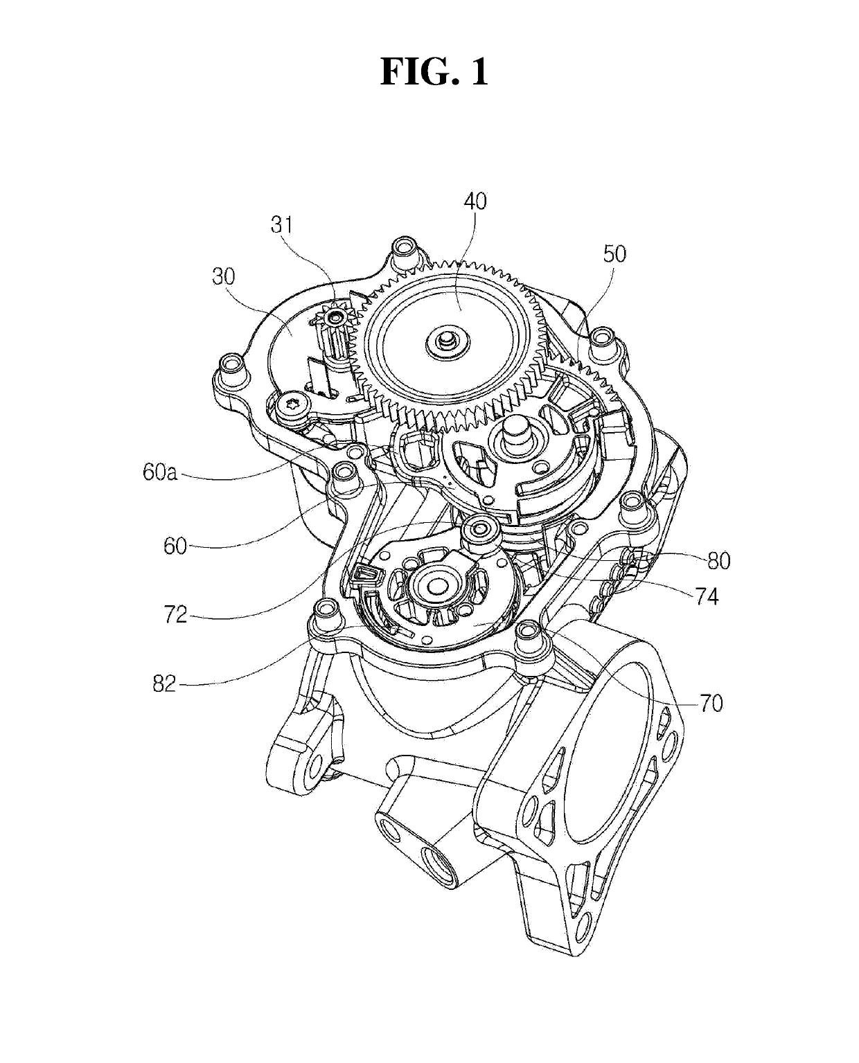
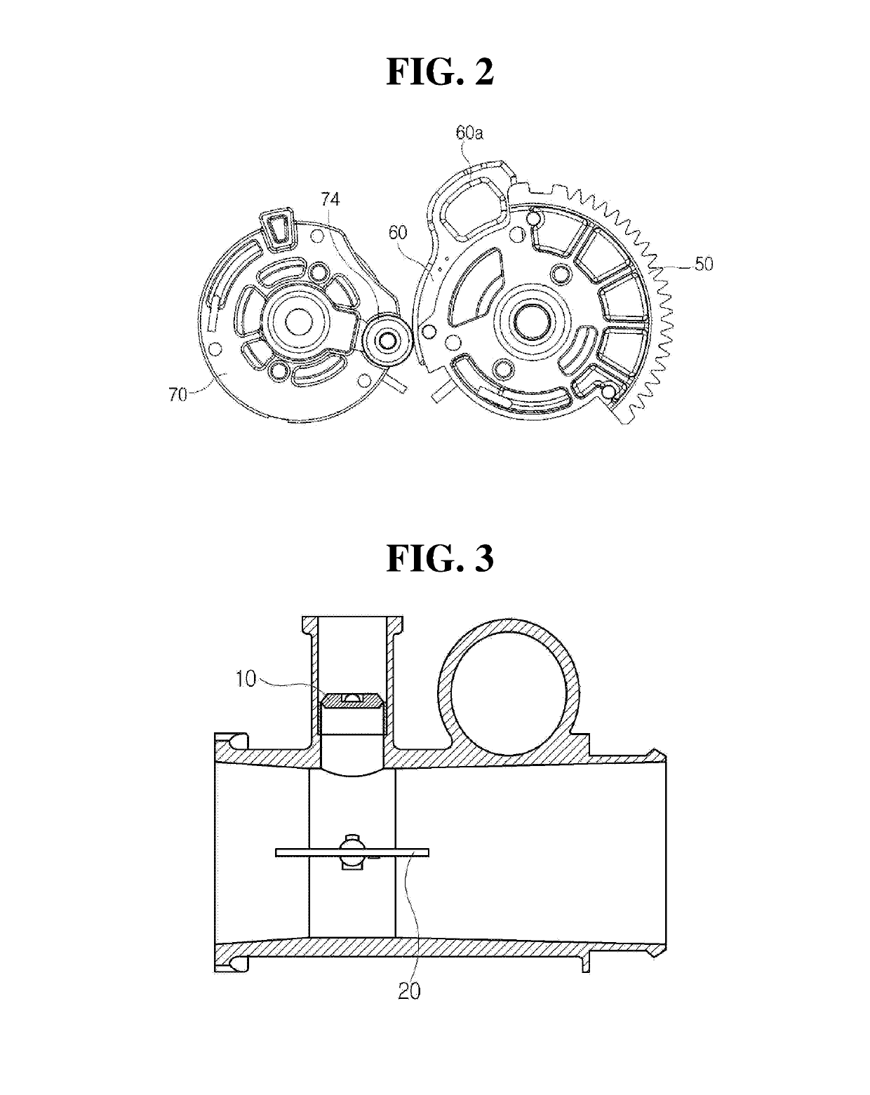
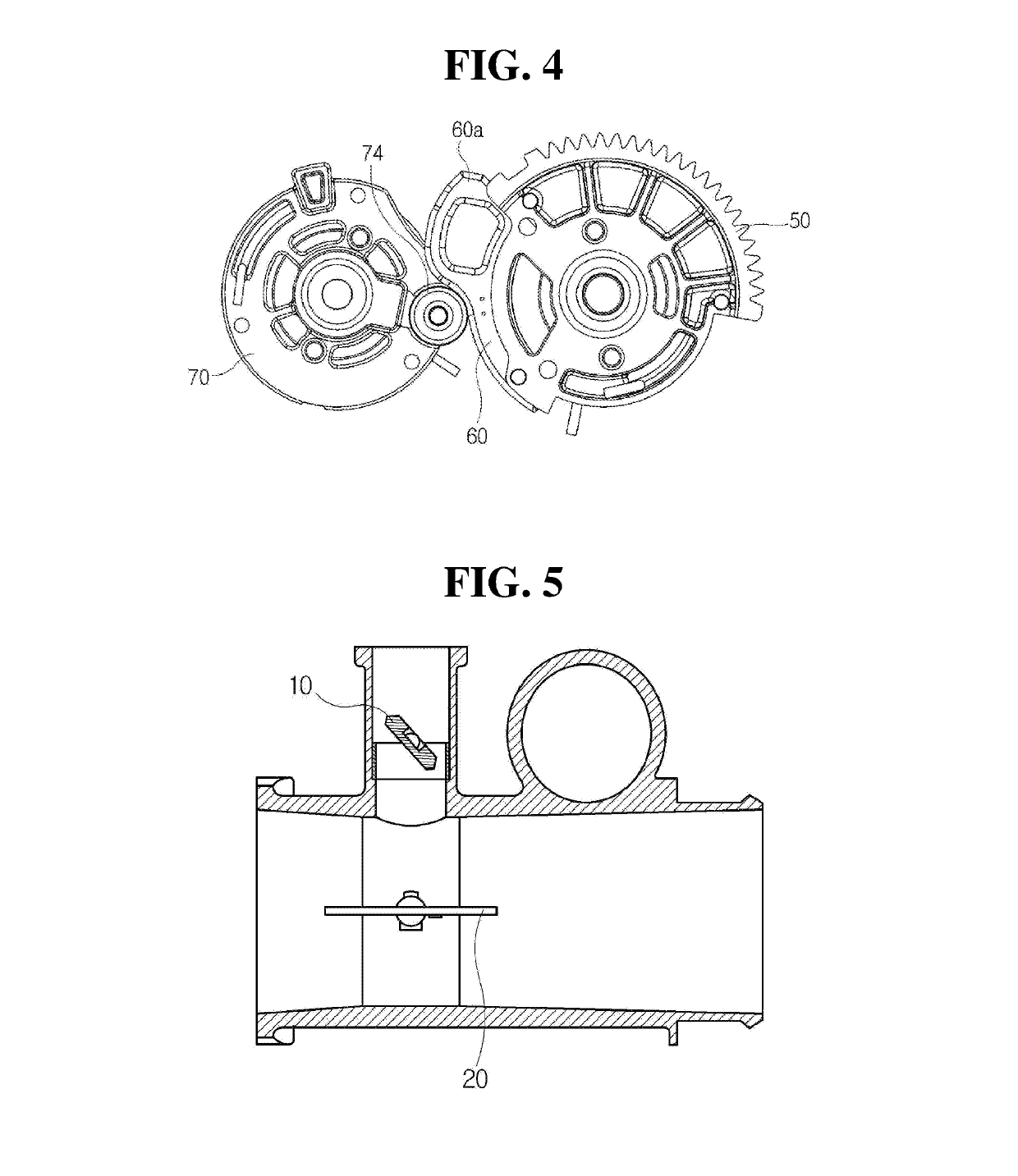
The present invention aims to provide an EGR valve unit that reduces contaminants, increases fuel efficiency, and prevents sudden fluctuations in engine output or stoppage. It achieves this by configuring the EGR valve such that even when there is an abnormality in the return spring of an air intake valve, the air intake valve can be returned back and controlled continuously. The cam profile aperture is designed to prevent interference with the inner surface when the segment gear and the rotation arm operate normally, and a gap is formed between the free end of the pin and the wall surface when the segment gear and the rotation arm are in default positions. The return guide provided in the segment gear ensures that the air intake valve always returns to the default position, regardless of any abnormalities in the return spring, allowing for uninterrupted control and prevention of fluctuations in engine output or stoppage.

Problems solved by technology

However, exhaust gas from diesel-engine vehicles contains harmful substances such as carbon monoxide (CO), hydrocarbons (HC) and oxides of nitrogen (NOx).
The oxides of nitrogen (NOx) among these substances are generated by a combination of oxygen and nitrogen at high pressure and high temperature and cause corrosion of buildings and destruction of ecosystems since they become a cause of acid rain and a cause of various respiratory diseases such as bronchitis, pneumonia and asthma in human bodies.

Method used


Image

  • Egr valve unit
  • Egr valve unit
  • Egr valve unit

Examples


Embodiment Construction

[0031]Although various modifications to the present disclosure may be made and the present disclosure may have various embodiments, exemplary embodiments of the present disclosure will be illustrated by way of example in the drawings and described in detail below. However, it is to be understood that these are not intended to limit the present disclosure to the exemplary embodiments but the present disclosure covers all modifications, equivalents and alternatives falling within the spirit and scope of the disclosure. It is noted that thicknesses of lines, dimension of components shown in the drawings and the like may be expressed exaggeratedly for clarity and convenience of description.

[0032]In addition, terms to be described below are those defined in consideration of functions in the present disclosure, which may vary depending on intention or custom of users or operators. Therefore, definition of these terms should be made based on the contents throughout this specification.

[0033...


PUM


Abstract

An EGR valve unit is provided. The EGR valve unit comprises a segment gear disposed on a shaft of an EGR valve, a rotation arm disposed on a shaft of an air intake valve, a bearing disposed on the rotation arm via a pin, and a cam member disposed on the segment gear and formed with a push part configured to push the bearing to rotate the rotation arm when the EGR valve is operated.

Description

CROSS-REFERENCE TO RELATED APPLICATIONS[0001]This application claims priority to Korean Patent Application No. 10-2017-0183778, filed on Dec. 29, 2017, the disclosure of which is incorporated herein by reference in its entirety.TECHNICAL FIELD[0002]The present disclosure relates to an EGR valve unit, and more particularly to an EGR valve unit that recirculates exhaust gas to an engine.RELATED ART[0003]Diesel engines are widely used in commercial vehicles such as passenger cars, buses and trucks and throughout the industries since the diesel engines have an improved fuel efficiency than gasoline engines. However, exhaust gas from diesel-engine vehicles contains harmful substances such as carbon monoxide (CO), hydrocarbons (HC) and oxides of nitrogen (NOx). The oxides of nitrogen (NOx) among these substances are generated by a combination of oxygen and nitrogen at high pressure and high temperature and cause corrosion of buildings and destruction of ecosystems since they become a caus...

Claims


Application Information

Patent Timeline
IPC IPC(8): F02M26/64F02M35/10
CPCF02M26/64F02M35/10373F02M35/10222Y02T10/12F02M26/67F02M26/70F02D2041/0017
Inventor CHO, UNG RAE
Owner HYUNDAI KEFICO CORP
Learn More