Method of removal of engine exhaust from a work machine and system thereof

Active Publication Date: 2019-10-10
DEERE & CO
View PDF1 Cites 1 Cited by
  • Summary
  • Abstract
  • Description
  • Claims
  • Application Information

AI Technical Summary

Benefits of technology

[0004]In one embodiment, there is provided a work machine including an implement and a hydraulic system configured to power the implement. The work machine includes an engine configured to provide power and to generate an exhaust as a result thereof and an oil cooling system configured to cool an oil of the hydraulic system. An engine cooling system is configured to cool an engine coolant circulating through the engine. An exhaust system is operatively connected

Problems solved by technology

The exhaust released to the atmosphere is at a high temperature which can irritate an operator of the vehicle, depending on the direction of the exhaust travels after being released.
The high temperature exh

Method used


Image

  • Method of removal of engine exhaust from a work machine and system thereof
  • Method of removal of engine exhaust from a work machine and system thereof
  • Method of removal of engine exhaust from a work machine and system thereof

Examples


Example

[0013]Corresponding reference numerals are used to indicate corresponding parts throughout the several views.

DETAILED DESCRIPTION

[0014]The embodiments of the present disclosure described below are not intended to be exhaustive or to limit the disclosure to the precise forms in the following detailed description. Rather, the embodiments are chosen and described so that others skilled in the art may appreciate and understand the principles and practices of the present disclosure.

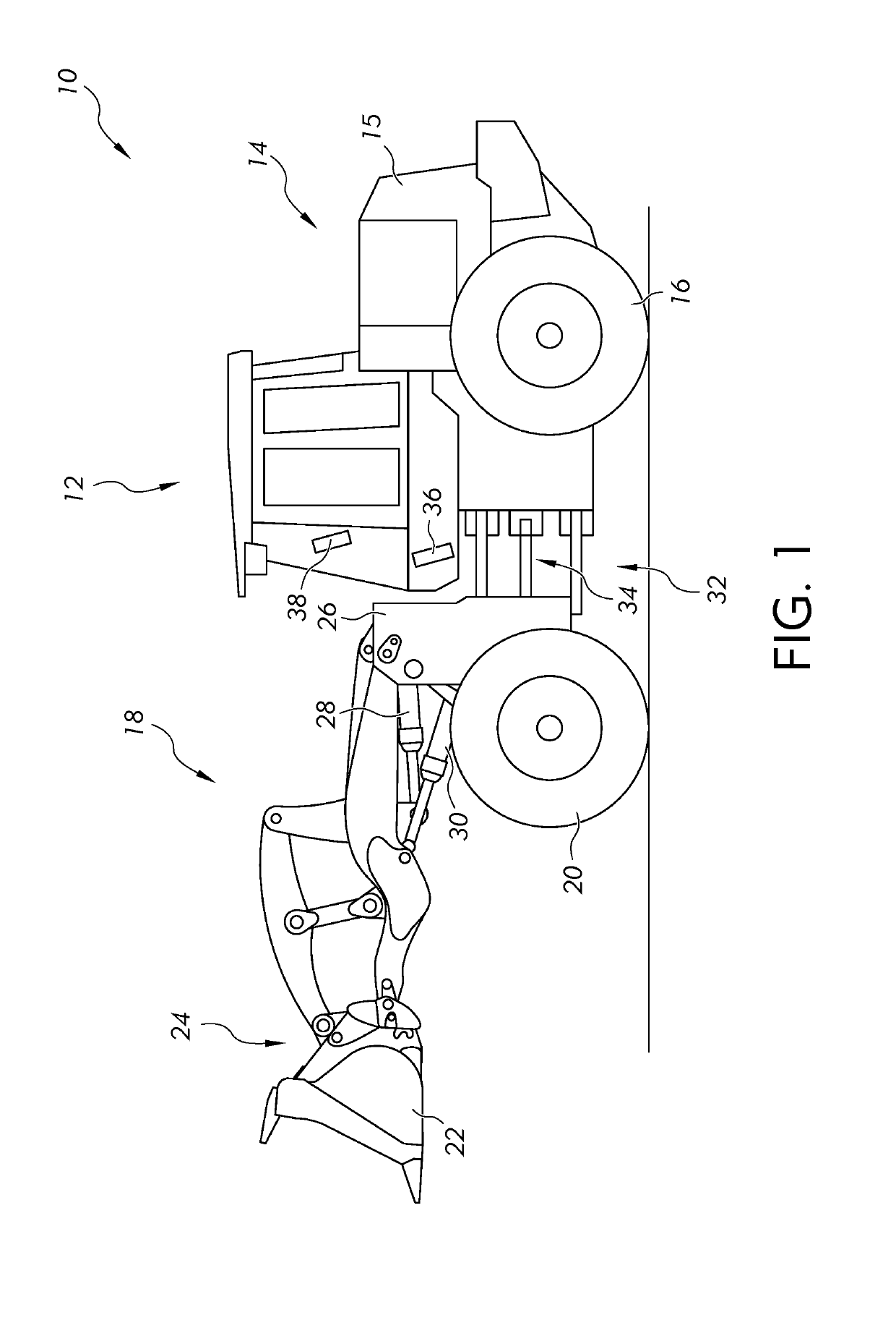
[0015]An example embodiment of a work machine is shown in FIG. 1. The machine is illustrated as a front loader 100 such as a four-wheel drive loader. The present disclosure is not limited, however, to a loader and may extend to other work machines such as an excavator, a backhoe loader, crawler, harvester, skidder, motor grader, or any other work machine. As such, while the figures and forthcoming description may relate to a loader, it is to be understood that the scope of the present disclosure extends beyond...


PUM


Abstract

An apparatus and method of cooling an engine exhaust generated by an engine of a work machine having a hydraulically operated implement. The work machine includes an emission control system and a cooling system having an oil cooling system configured to cool an oil of a hydraulic system and an engine cooling system configured to cool an engine coolant circulating through the engine. An exhaust pipe, coupled to the emission control system and configured to direct engine exhaust, includes an outlet disposed in a space located between an oil cooler of the oil cooling system and a radiator of the engine cooling system. An air displacement device is configured to draw air into and away from the oil cooler and the radiator and to draw the exhaust from the exhaust pipe. Exhaust from the exhaust pipe is drawn past the oil cooler and the radiator to cool the exhaust.

Description

FIELD OF THE DISCLOSURE[0001]The present disclosure relates to a work machine, and in particular, to a method of removal of engine exhaust from the work machine and a system thereof.BACKGROUND OF THE DISCLOSURE[0002]Many work machines, such as a front loader, include one or more implements capable of performing a work function. A front loader includes a prime mover which generates power to perform work, a shaft power conversion machine, and reversible energy storage. In the case of a four wheel drive loader, for instance, the prime mover is often a diesel engine that generates power from a supply of diesel fuel. The diesel engine drives a transmission which moves a ground engaging traction device, such as wheels or treads, to propel the loader, in some situation, across unimproved ground for use in construction. Such loaders include a hydraulic machine having a hydraulic pump which can be used for instance, to raise or lower a piece of equipment such as a bucket. The bucket is coupl...

Claims


Application Information

Patent Timeline
IPC IPC(8): F01P11/10F15B21/04F01N3/02F01N3/08F01N3/021
CPCF01P11/10F01N3/021F15B21/042F01N3/08F01N3/0205E02F9/0841E02F9/0866F01N3/02F01N3/05F01N13/082F01N2270/08F01P3/18F01P11/08Y02A50/20Y02T10/12
Inventor KENNEDY, THOMASCAMPBELL, KEVIN W.WANTSCHIK, PAUL A.GRABER, TRAVISAIREY, KAL J.
Owner DEERE & CO
Why Eureka
Try Eureka