Epicyclic reducer for a wheel hub and vehicle

US20220107004A1Pending Publication Date: 2022-04-07IVECO SPA
0 Cites 0 Cited by

Patent Information

Authority / Receiving Office
US · United States
Current Assignee / Owner
Publication Date
2022-04-07

Smart Images

  • Figure 1
    Figure 1
  • Figure 2
    Figure 2
  • Figure 3
    Figure 3
Patent Text Reader

Abstract

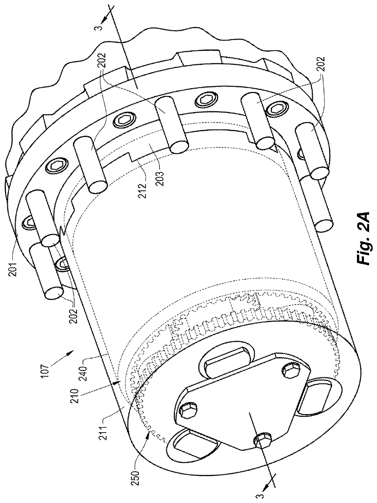
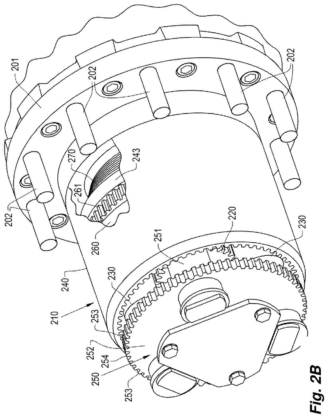
The invention relates to an epicyclic reducer for a vehicle hub that includes: a housing; a sun gear arranged in the housing that includes sun teeth and is configured for coupling to an input; a plurality of planet gears, each of which includes planet teeth meshed with some of the sun teeth; a planet carrier that couples the planet gears to each other and is configured as an output; and a ring gear that includes ring teeth meshed with some of the planet teeth of each of the planet gears. The ring gear can be moved within the housing between a reduction position in which the planet gears are configured to rotate relative to the ring gear, and a direct drive position in which the ring gear is constrained to rotate with the planet gears.
Need to check novelty before this filing date? Find Prior Art

Description

BACKGROUND OF THE INVENTION

[0001] The present invention relates to vehicles and, in particular, to epicyclic reducers for them.

[0002] Vehicles, such as trucks, are often used to tow heavy loads. Such a vehicle generally includes a heat engine, which is coupled to the drive wheels through a transmission. The transmission generally features a gearbox that rotatably couples a drive shaft to the engine. The half shafts, which are used to drive the wheels, are rotatably coupled to the drive shaft, for example, by means of one or more differentials. The half shafts turn a wheel hub, which is connected to the wheels to rotate them. This allows the rotary engine to give power to the wheels to rotate them and move the vehicle.

[0003] For trucks and other large vehicles, it is known to provide two-stage speed reduction in order to rotate the wheels at a lower rotational speed than that of the engine and increase their torque. The first stage of reduction generally takes place in the gearbox. Howe...

Examples

Embodiment Construction

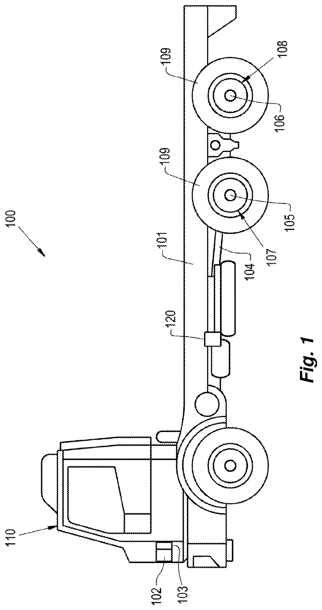
[0020]Referring now to the Figures, and more particularly to FIG. 1, an exemplary embodiment of a vehicle 100 formed in accordance with the present disclosure is illustrated. In the illustrated embodiment, the vehicle 100 is a truck that includes a chassis 101 and a thermal machine, such as an engine 102, carried by the chassis 101. The engine 102 can be an internal combustion engine, for example, driven by chemical fuel, such as petrol or diesel, stored in a tank, an electric motor powered by current from a battery, or a hybrid combination output from either an internal combustion engine or an electric motor. A gearbox 103 is provided to transmit output power from the motor 102 to a rotatably coupled drive shaft 104. It is a well-known fact that the gearbox 103 can provide a first stage of speed reduction from the motor 102 to the drive shaft 104. The drive shaft 104 is rotatably coupled to one or more half shafts 105, 106, for example, by means of one or more differentials carried...