
Reciprocating piston mechanism with extended piston offset

Inactive Publication Date: 2012-08-23
INDEN MICHAEL
View PDF7 Cites 2 Cited by
  • Summary
  • Abstract
  • Description
  • Claims
  • Application Information

AI Technical Summary

Benefits of technology

[0014]It is another object of this invention to provide a reciprocating piston mechanism which will reduce relationship between a piston stroke and the length of the driveshaft / crankshaft moment arm.
[0016]It is another object of this invention to provide a reciprocating piston mechanism for an internal combustion engine which increases fuel efficiency for the required engine power output.
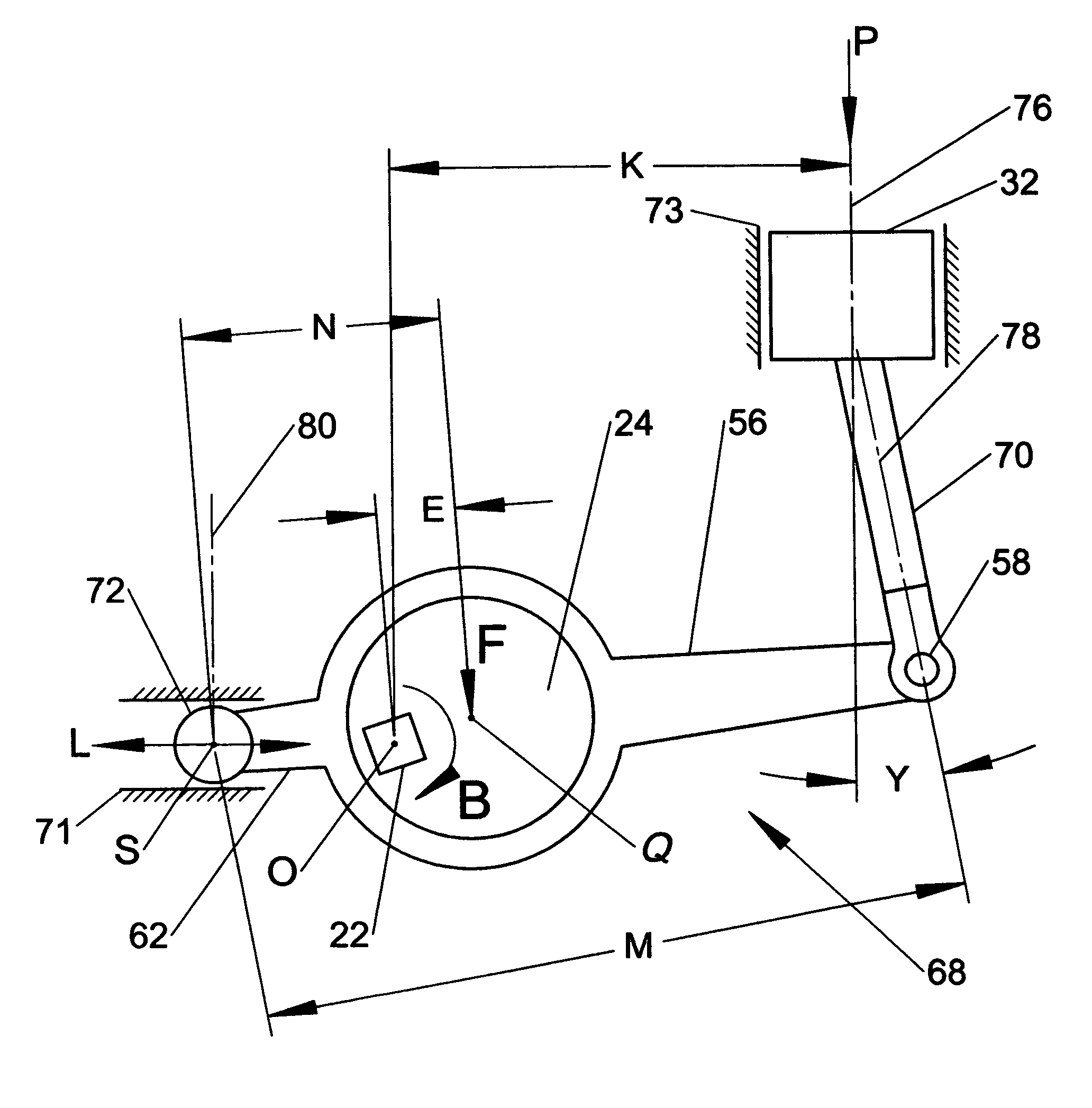
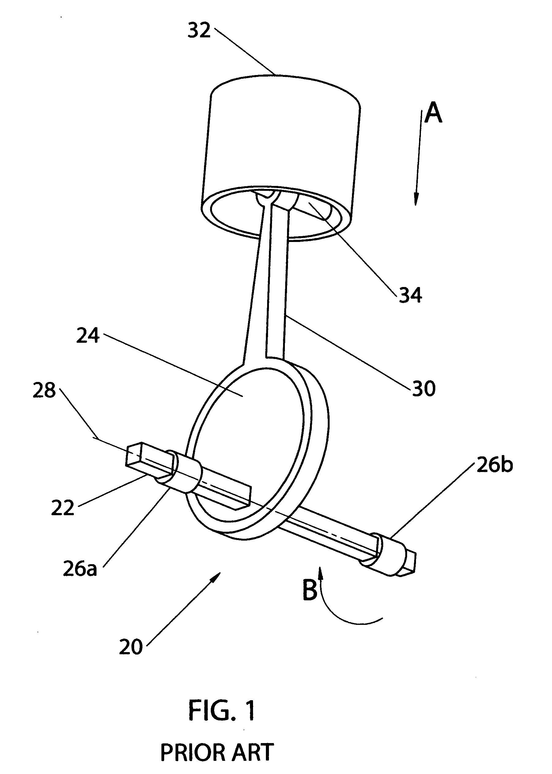
[0017]It is yet another object of the invention to provide a reciprocating piston mechanism for an internal combustion engine which is simple in design and inexpensive to manufacture. The reciprocating piston mechanism of the present invention, e.g., for an internal combustion engine with extended piston offset, is of the type that contains at least one cylinder having a longitudinal axis, at least one piston that has a pivot pin and is slidingly installed in the cylinder, a main driveshaft having a central axis, which is offset at a distance from the longitudinal axis of the cylinder, a circular cylindrical body, e.g., a circular eccentric, which is non-rotationally secured on the main drive shaft, a rocker arm, which in essence is a second order lever, pivotally mounted on the said circular eccentric and a connecting rod connecting the cylinder and one arm of the rocker arm / lever. The other arm of the rocker arm / lever can move back and forth only along a substantially defined line in a confined pathway or a guide and works as a stabilizer / rudder. In other words, a distinguishing feature of the reciprocating piston mechanism of the invention with extended piston offset is the rocker arm / lever that has a substantially circular opening which pivotally receives the circular eccentric and a fulcrum which moves along a substantially defined line in the guide during rotation of the driveshaft. The distance from the central axis of the main driveshaft and the longitudinal axis of the cylinder is always greater than 0. Such a construction significantly improves torque applied to the driveshaft and efficiency of the engine.

Problems solved by technology

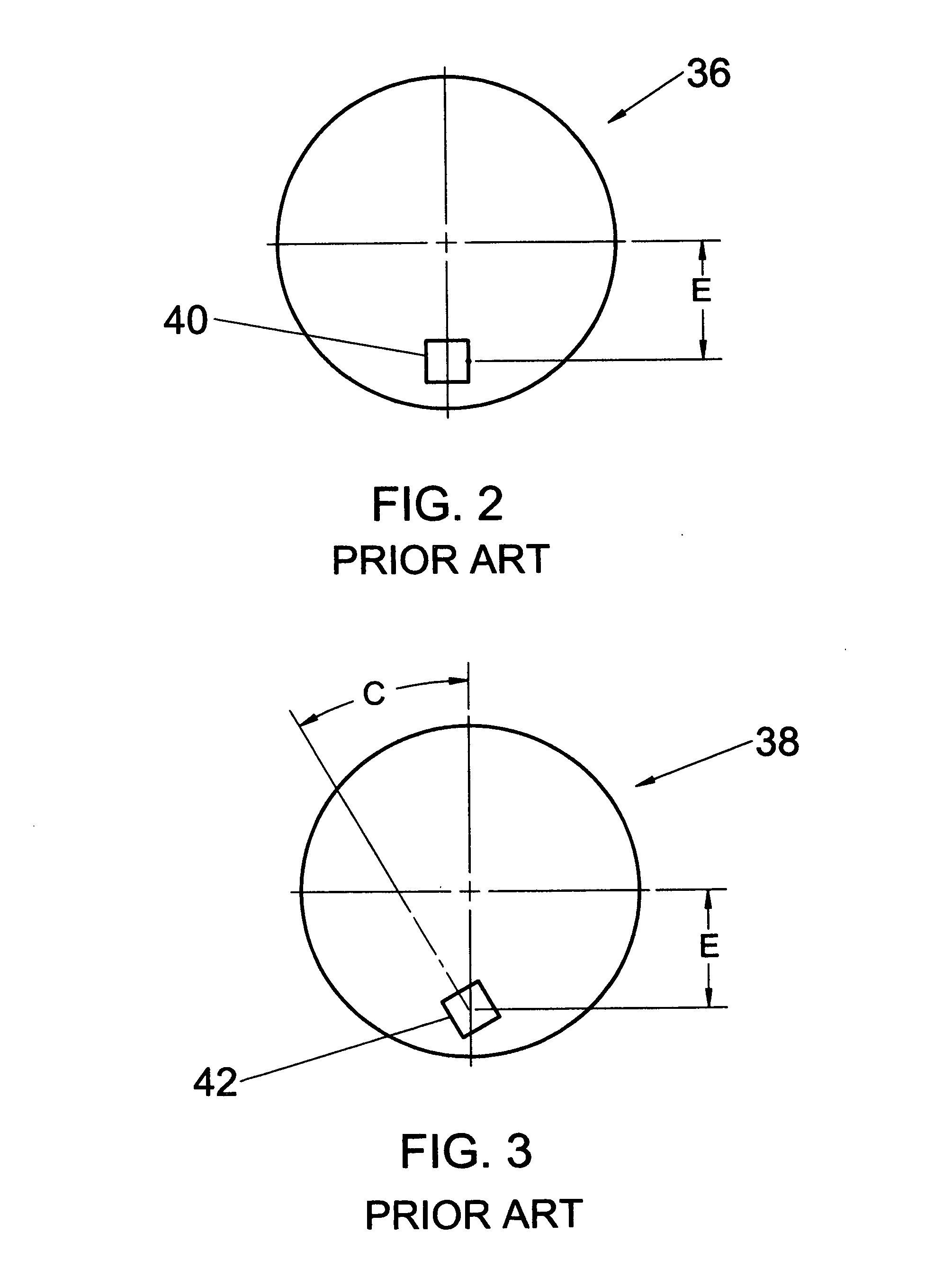
In these particular configurations with the offset connecting rod, increase in the crankshaft rotating force is negated by significantly increased friction loses between the piston and the cylinder.
Thus, none of the above mentioned approaches which involves laterally offset of the axis of rotation of the crankshaft from the axis of the piston cylinder, allows any significant improvement of the torque created by the rotation of the crankshaft and consequently engine power and efficiency without significant enlargement of the crankshaft.
All of this leaves little room for an engineer to influence the output power.

Method used


Image

  • Reciprocating piston mechanism with extended piston offset
  • Reciprocating piston mechanism with extended piston offset
  • Reciprocating piston mechanism with extended piston offset

Examples


Embodiment Construction

[0030]The basic components of a reciprocating piston mechanism are well known in the art and include at least one cylinder, one piston, a connecting rod and a crankshaft. For better understanding the distinguishing features of the present invention, it would be appropriate to again refer to the structure of a connecting rod used in an internal combustion engine which was disclosed in U.S. patent application Ser. No. 12 / 151,954 filed earlier by the same applicant and the improvement of which the present application is aimed. More specifically, FIG. 4 illustrates an exemplary embodiment of a connecting rod 30 of a crankshaft-free driveshaft and piston assembly of a split-cycle four-stroke engine. The connecting rod 30 comprises a straight arm 44 connecting a small distal end 48 for attachment to a piston pin (not shown in FIG. 4) and a big end 46 for pivotally connecting to a circular eccentric (not shown in FIG. 4). In a mechanism with this type of a connecting rod, piston stroke and...


PUM


Abstract

The reciprocating piston mechanism with an extended piston offset is provided. The mechanism is of the type that contains at least one cylinder having a longitudinal axis, at least one piston that has a pivot pin and is slidingly installed in the cylinder, a main driveshaft having a central axis, which is offset at a distance from the longitudinal axis of the cylinder, a circular cylindrical body, e.g., a circular eccentric, which is non-rotationally secured on the main drive shaft and a rocker arm, which in essence is a second order lever. The lever is pivotally mounted on the circular eccentric. The mechanism is also provided with a connecting rod that connects the cylinder to one arm of the rocker arm / lever. The other arm of the rocker arm / lever has a roller that is guided in a confined pathway and works as a fulcrum of the lever and a stabilizer / rudder at the same time.

Description

TECHNICAL FIELD[0001]The present invention relates to a reciprocating piston mechanism such as an internal combustion engine, compressor, pump or the likes. More specifically, the present invention relates to modular sub-assemblies for an internal combustion engine, compressor, pump or the likes which include a driveshaft, a circular eccentric mounted on the driveshaft and a piston with an offset between the piston cylinder center line and the driveshaft axis. This altered geometrical relationship provides increased power and torque for an internal combustion engine.BACKGROUND OF THE INVENTION[0002]Internal combustion engines are any of a group of devices in which the reactant of combustion, e.g., oxidizer and fuel, and the products of combustion serve as the working fluids of the engine. Internal combustion (IC) engines can be categorized into spark ignition (SI) and compression ignition (CI) categories. SI engines, i.e. typical gasoline engines, use a spark to ignite the air-fuel ...

Claims


Application Information

Patent Timeline
IPC IPC(8): F01B9/00
CPCF01B9/02F02F7/0019F04B53/006F04B35/01F04B39/0094F04B9/045
Inventor INDEN, MICHAEL
Owner INDEN MICHAEL
Learn More