Drive Control Device for Work Vehicle

Active Publication Date: 2014-01-02
HITACHI CONSTR MASCH CO LTD
View PDF6 Cites 9 Cited by
  • Summary
  • Abstract
  • Description
  • Claims
  • Application Information

AI Technical Summary

Benefits of technology

[0019]The present invention sends to an engine a target engine speed command, which has been obtained by adding an engine stall-preventing increment of target engine speed to a target engine speed set corresponding to a depression stroke of an accelerator pedal, when a forward/reverse command from a forward/reverse command means is determined to have been received and the speed of a working vehicle is determined to be not higher than a threshold value which has been stored beforehand. It is, therefore, possible to always maintain the engine torque greater than engine load torque and also to prevent engine stall with certainty even with respect to an emission control compliant engine restricted in fuel injection volume.
[0020

Problems solved by technology

Emission control compliant engines lack so-called tenacity, and are liable to stall when subjected to a large load.
Especially in a working vehicle of the torque converter drive system like a wheel loader of the torque converter drive system that an output torque from an engine is transmitted to a transmission via a torque converter to generate traveling drive force, the engine is liable to stall because for its work characteristics, a high load tends to act on the engine even in a state that an accelerator is not depressed.
In such a situation, a load by its own weight or an inertia force acts on the engine via tires,

Method used


Image

  • Drive Control Device for Work Vehicle
  • Drive Control Device for Work Vehicle
  • Drive Control Device for Work Vehicle

Examples


Embodiment Construction

[0033]Taking, as an example, a drive control system for a wheel loader, a drive control system according to an embodiment for a working vehicle will hereinafter be described with reference to the drawings.

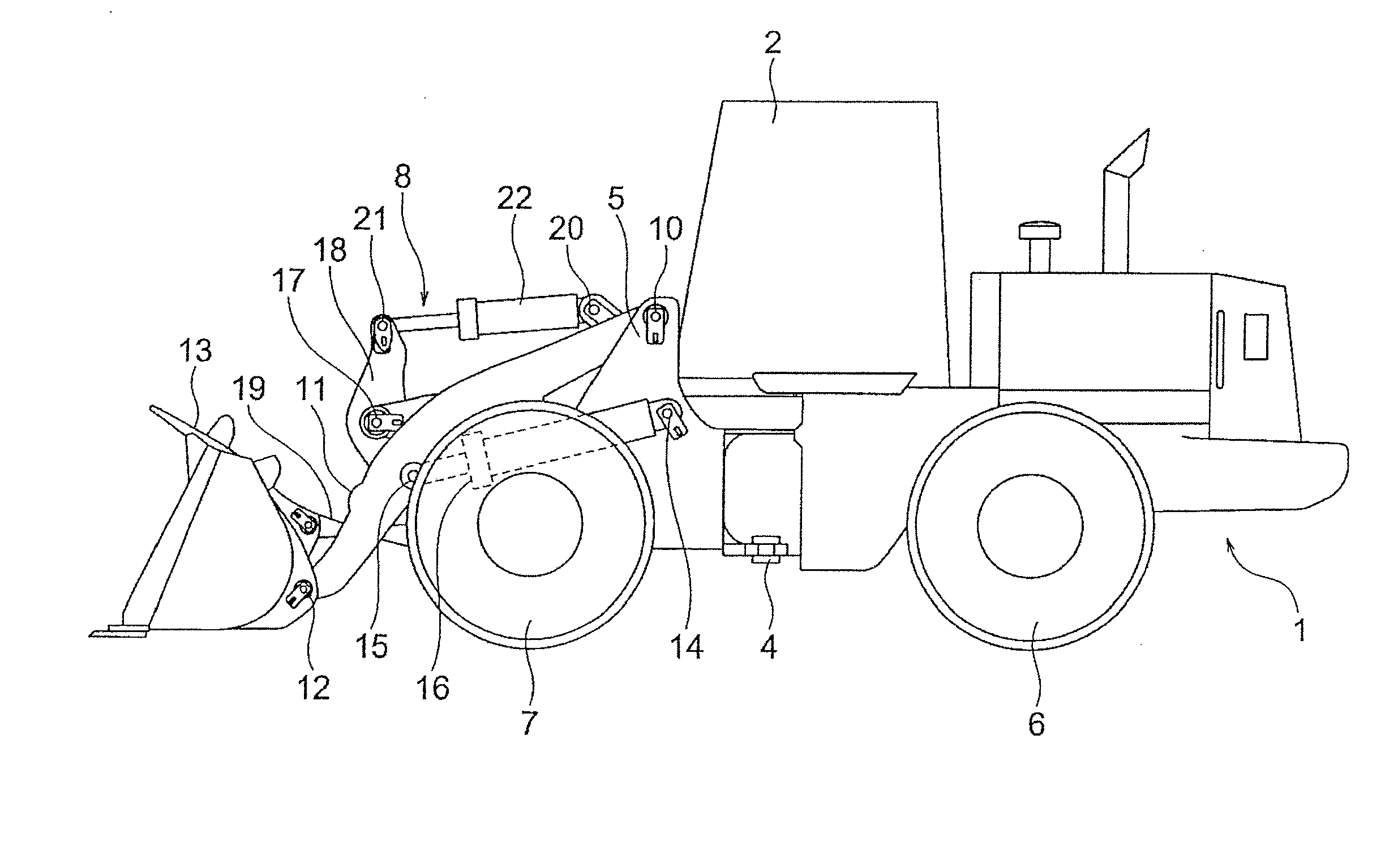
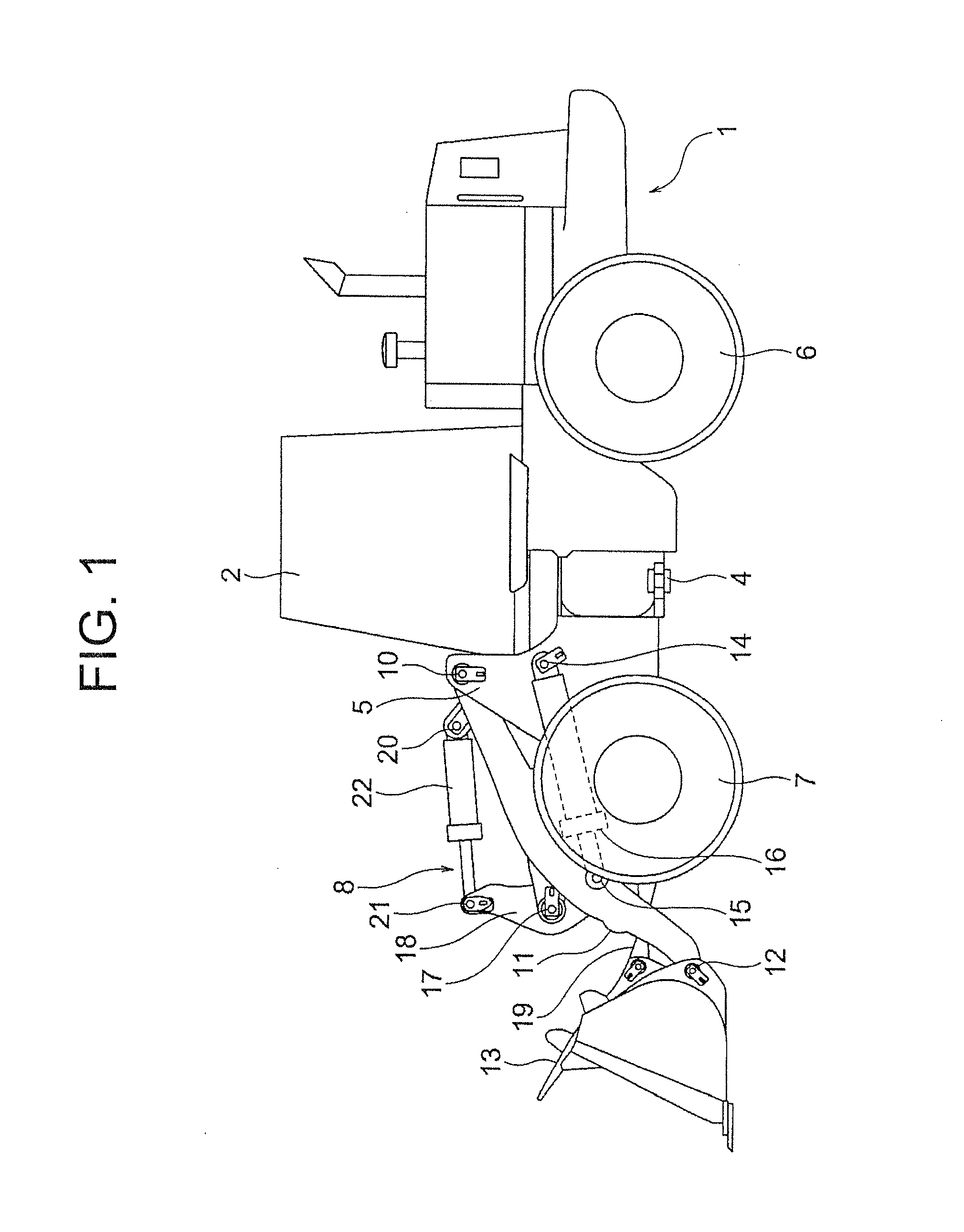
[0034]As depicted in FIG. 1, the wheel loader 1 to which the drive control system of this embodiment is applied is constructed primarily of a rear body 3 provided with an operator's cab 2, a front body 5 joined to a front side (a forward side of the wheel loader 1) of the rear body 3 via a joint pin 4, wheels 6,7 arranged on these rear body 3 and front body 5, and front working equipment 8 attached to a front part of the front body 5. The front body 5 is constructed to be laterally articulatable about the joint pin 4 as a center relative to the rear body 3. The wheel loader 1 is, therefore, allowed to change its forward direction by manipulating an unillustrated steering device arranged in the operator's cab 2 and articulating the front body 5 in a left direction or right direction...


PUM


Abstract

To provide a drive control system for a working vehicle, which can prevent engine stall with certainty even when a large load suddenly acts on a vehicle-mounted engine and which is also excellent in environment friendly performance.
When a vehicle speed of a wheel loader (1) is determined to be not higher than a reference value (Yes) in step S4 and a forward/reverse command means (40) is determined to have been switchingly operated (Yes) in step S5, the routine advances to step S6 where an increment ΔN of engine speed according to an engine load factor is determined. In step S7, the increment ΔN of engine speed is then added to a target engine speed Na corresponding to a depression stroke of an accelerator pedal (38), the thus-determined Na=Na+ΔN is set as a new target engine speed Na, and a target engine speed command i1 is sent to an engine controller (37).

Description

TECHNICAL FIELD[0001]This invention relates to a drive control system for a working vehicle, and specifically to a stall prevention means suitable for a working vehicle with an engine mounted thereon and restricted in fuel injection volume in compliance with emission control.BACKGROUND ART[0002]Working vehicles such as wheel loaders are also subjected to emission control, and working vehicles with engines mounted thereon and restricted in fuel injection volume to meet emission control are conventionally known. Emission control compliant engines lack so-called tenacity, and are liable to stall when subjected to a large load. Especially in a working vehicle of the torque converter drive system like a wheel loader of the torque converter drive system that an output torque from an engine is transmitted to a transmission via a torque converter to generate traveling drive force, the engine is liable to stall because for its work characteristics, a high load tends to act on the engine even...

Claims


Application Information

Patent Timeline
IPC IPC(8): E02F9/20
CPCE02F9/2066F02D29/00F02D29/04B60W30/18036B60W30/1884B60W2520/06B60W2520/10B60W2540/10B60W2710/0644B60Y2200/41B60W30/1886B60W2552/15
Inventor TANAKA, TETSUJIHYODO, KOJIAOKI, ISAMUKIKUCHI, KEIGO
Owner HITACHI CONSTR MASCH CO LTD
Why Eureka
Try Eureka