Push plate, mounting assembly, circuit board, and method of assembling thereof for ball grid array packages

a technology of mounting assembly and grid array, which is applied in the direction of coupling parts engagement/disengagement, coupling device connection, instruments, etc., can solve the problems of increasing the risk of accidentally bridging adjacent pins with solder, increasing the risk of rework, and rework, so as to minimize the interference around the package, minimize the effect of torqu

Active Publication Date: 2017-05-16
NAT TECH & ENG SOLUTIONS OF SANDIA LLC
View PDF2 Cites 7 Cited by
  • Summary
  • Abstract
  • Description
  • Claims
  • Application Information

AI Technical Summary

Benefits of technology

[0019]In an embodiment of the present invention, a push plate is disclosed that provides a known, uniform, down force, minimizes torque, and that does not interfere with access to the top of a ball grid array package, while assembling and / or testing a ball grid array package, hereafter referred to as “package”. The package may be a conventional ball grid array package, such as microprocessors, application specific integrated circuits (ASIC), memories and MCMs, used for microprocessors and / or field programmable gate arrays. In an embodiment, the package may be a MCM. In an embodiment, the push plate is used to assemble a package to a socket or PCB that has spring pins that push up under the balls. The push plate has a large viewing window and a minimum thickness so as not to interfere with the visual inspection of the package. The minimum thickness also minimizes interference around the package.
[0020]The push plate provides a uniform, down force with minimal torque by suspending a down-load frame with double cantilever flexures. The cantilevers have a known, calculable down force producing stiffness, while providing a calibrated down force. The central slit length of the flexures can be lengthened or shortened to produce the desired torque stiffness and / or to minimize torque. This effect is enhanced by intrinsically doubling the cantilevers geometrically.
[0021]An advantage of the present disclosure is to provide a push plate having direct visual access to the package.
[0022]Another advantage of the present disclosure is to provide a push plate that applies uniform, down force to the package during assembly with the package holder.

Problems solved by technology

As package pins get closer together, the danger of accidentally bridging adjacent pins with solder increases.
Existing sockets for BGAs, often needed during development, burn-in, rework, inspection, troubleshooting, and testing tend to be unreliable.
The less reliable type is a ZIF socket, with spring pinchers that grab the balls.
Neither of these systems work well, without sufficient uniform downward force applied to the MCM package or integrated circuit, especially if the balls are small.
These push plates illustrate the root of the problem in using these typical push plates, in that these existing methods to clamp the ball grid array package to the temporary socket are clumsy and block access to the ball grid array package.
This holding force must be applied uniformly to the ball grid array package, without large torques, since torques can cause excessive force along an edge or at a corner of the solder ball array, causing damage.
In addition to these force and torque requirements, there are many instances where physical access to the top of some portion of the ball grid array package chips is needed, for example for failure analysis applications, and this is universally not possible with current sockets, as pointed out previously.
Current push plate methods do not allow this access because of the methods used to supply the down force.
This application has the same problems associated with the inspection and temporary socket application described above, limited visual access to the ball grid array package and uneven force applied to the mounted ball grid array package.

Method used


Image

  • Push plate, mounting assembly, circuit board, and method of assembling thereof for ball grid array packages
  • Push plate, mounting assembly, circuit board, and method of assembling thereof for ball grid array packages
  • Push plate, mounting assembly, circuit board, and method of assembling thereof for ball grid array packages

Examples


Embodiment Construction

[0036]The present invention now will be described more fully hereinafter with reference to the accompanying drawings, in which preferred embodiments of the invention are shown. This invention may, however, be embodied in many different forms and should not be construed as limited to the embodiments set forth herein; rather, these embodiments are provided so that this disclosure will be thorough and complete and will fully convey the scope of the invention to those skilled in the art.

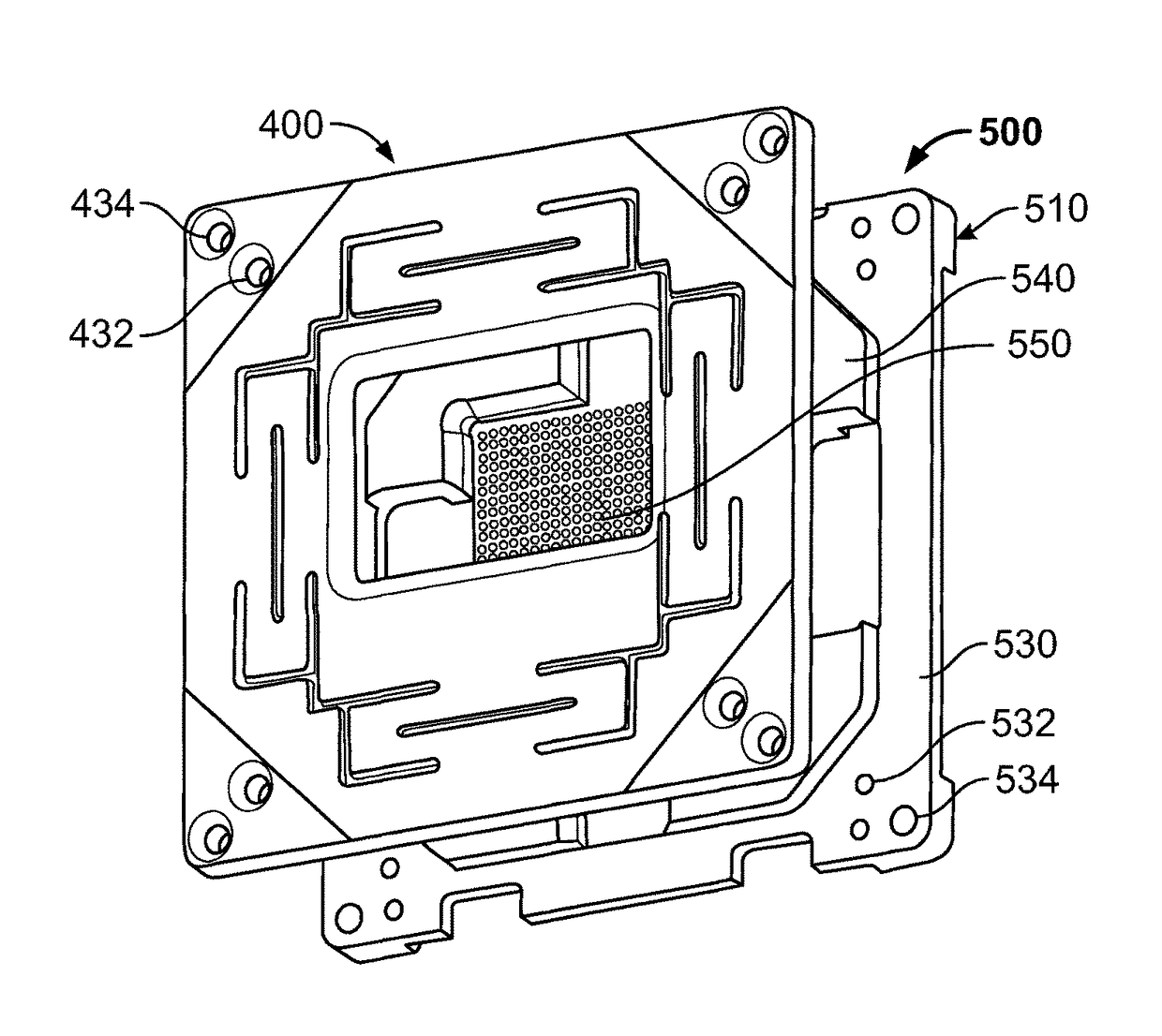
[0037]The present disclosure is directed to a push plate having a known down force, minimal torque, that does not interfere with access to the top of a package, and has minimum thickness. This is accomplished by suspending a down load frame with double cantilever flexures. The cantilevers have a known, calculable down force producing stiffness. While providing a calibrated down force, a central slit length can be lengthened or shortened to produce a desired torque stiffness to minimize torque. This effec...


PUM


Abstract

A push plate that includes springs in the form of cantilever flexures and an inspection window is disclosed. The push plate provides a known, uniform, down force and minimal torque to a package to be tested. The cantilevers have a known, calculable down force producing stiffness. The window provides for viewing of the package during testing.

Description

CROSS-REFERENCE TO RELATED APPLICATIONS[0001]This application claims priority to U.S. Provisional Patent Application 61 / 599,321, entitled “PUSH PLATE, MOUNTING ASSEMBLY, CIRCUIT BOARD, AND METHOD OF ASSEMBLING THEREOF FOR BALL GRID ARRAY PACKAGES,” filed Feb. 15, 2012, the specification thereof is incorporated herein by reference in the entirety.STATEMENT OF GOVERNMENT INTEREST[0002]The United States Government has rights in this invention pursuant to Contract No. DE-AC04-94AL85000 between the United States Department of Energy and Sandia Corporation, for the operation of the Sandia National Laboratories.FIELD[0003]The present disclosure is generally directed to a device for attaching a ball grid array package assembly to a test socket or printed circuit board, and more particularly to a low profile, controlled force, minimal torque push plate for ball grid array multi-chip module test sockets.BACKGROUND[0004]Ball grid array (BGA) packages, such as multi-chip modules (MCMs), are sma...

Claims


Application Information

Patent Timeline
Patent Type & Authority Patents(United States)
IPC IPC(8): H01R13/62H01H13/50H05K3/30H01R13/639
CPCH01H13/50H05K3/303H01R13/62H01R13/639G01R1/0466G01R1/0483
Inventor VAUGHN, MARK R.MONTAGUE, STEPHEN
Owner NAT TECH & ENG SOLUTIONS OF SANDIA LLC
Why Eureka
Try Eureka