Position and adjustment device using laser module

Inactive Publication Date: 2005-09-06
QUARTON IN
View PDF3 Cites 7 Cited by
  • Summary
  • Abstract
  • Description
  • Claims
  • Application Information

AI Technical Summary

Benefits of technology

[0019]Thus, the rolling characteristic of the rotating balls minimizes any torque that will be generated between the bolts and the laser module when adjusting the bolts, such that the laser mod

Problems solved by technology

Unfortunately, vibrations can cause the laser module inside a laser positioning to be biased, thereby causing the emitted laser beam to be inaccurate.
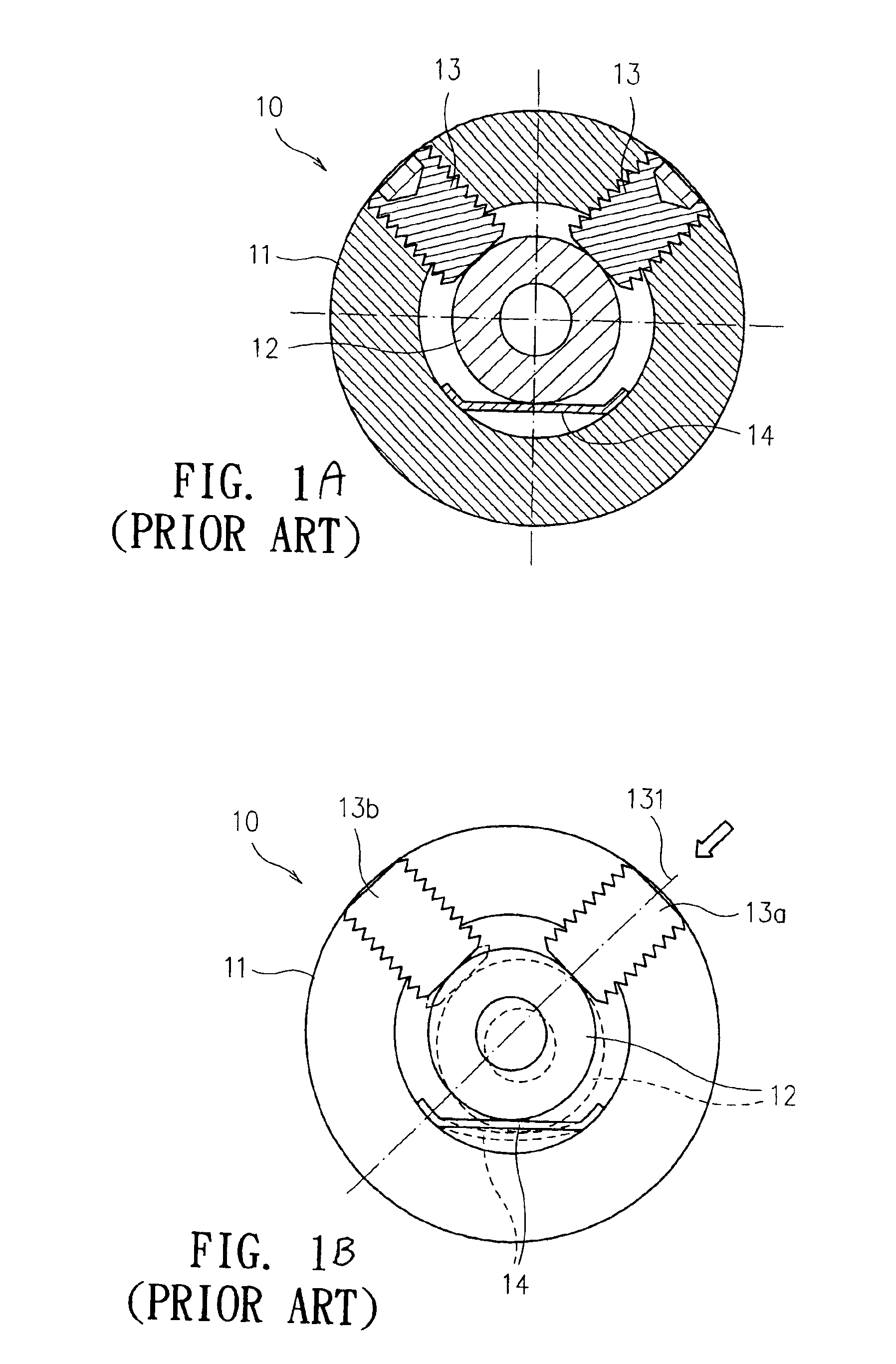
1. The contacting surface between the laser module 12 and the bolt 13 is arc-shaped. Therefore, if only one bolt 13 is adjusted, then a torque will be generated so that the laser module 12 cannot move in a linear manner. This is best illustrated in FIG. When one bolt 13a is screwed in, the most ideal case is that the laser module 12 should move linearly along the axial direction 131 of the bolt 13a. However, since the surface of the laser module 12 is arc-shaped, a torque will be generated with respect to the surface of the laser module 12 when adjusting the bolt 13a, such that the laser module 12 is biased or even rotated to move away from the axial direction 131 of the bolt 13a. Therefore, it is necessary to adjust another bolt 13b to counter the torque generated by the first bolt 13a. Unfortunately, it is extremely difficult, time-consuming and labor-intensive to simultaneously and accurately adjust both bolts 13a, 13b.
2. After extended use, the elastic piece 14 will experience elastic fatigue, thereby rendering the adjustment device 10 inoperable.
3. The stability of the laser module 12 is poor when the laser module 12 is in use. This is because it is easy for the laser module 12 to generate backward, forth, leftward, and rightward movements or even to rotate if the device 10 experiences vibration.
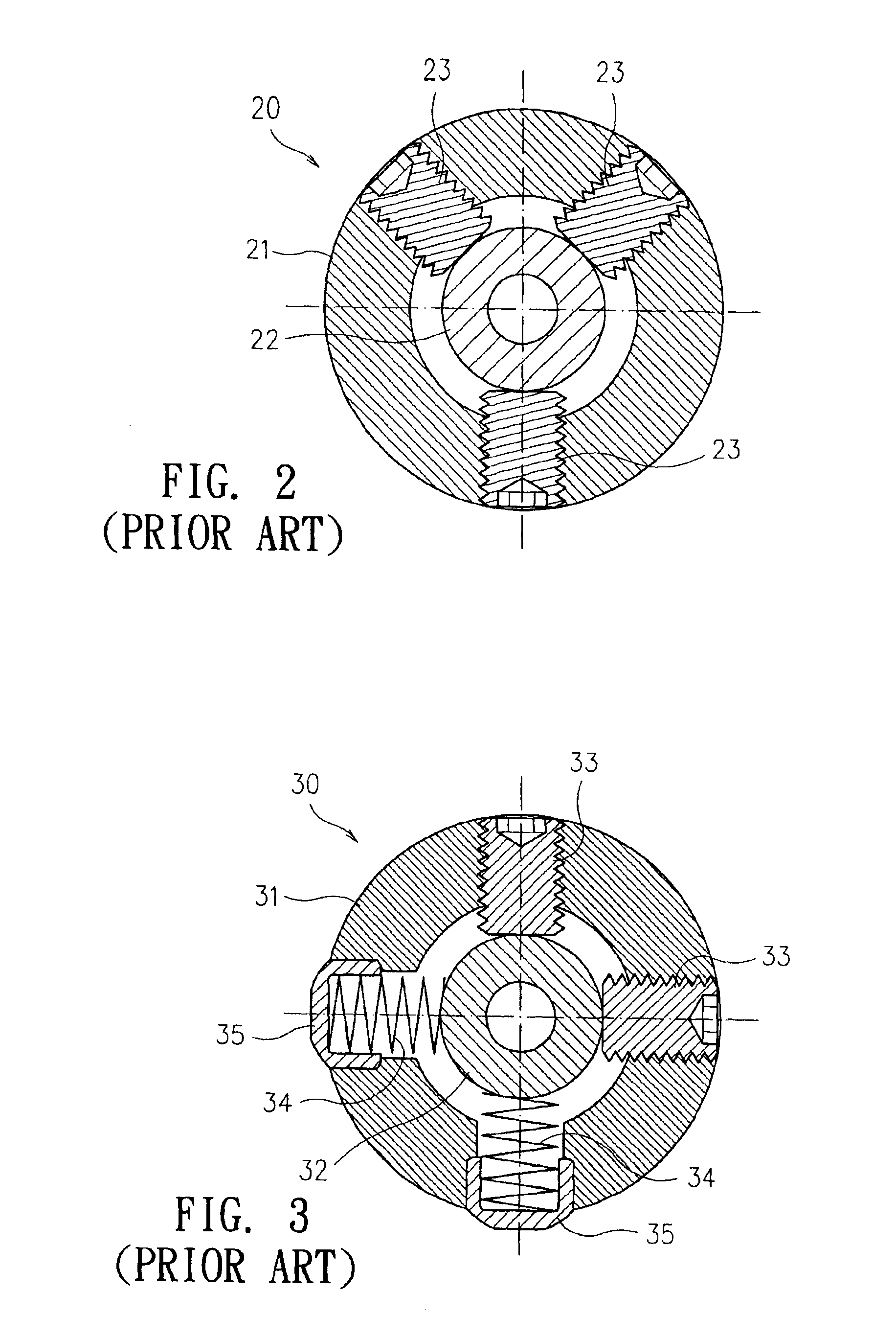
1. Although the provision of three spaced

Method used


Image

  • Position and adjustment device using laser module
  • Position and adjustment device using laser module
  • Position and adjustment device using laser module

Examples


Example

[0029]The following detailed description is of the best presently contemplated modes of carrying out the invention. This description is not to be taken in a limiting sense, but is made merely for the purpose of illustrating general principles of embodiments of the invention. The scope of the invention is best defined by the appended claims.

[0030]FIGS. 4-6 illustrate a position and adjustment device 40 according to one embodiment of the present invention. The device has a generally cylindrical body 41 with an internal bore 49. A laser module 42 is positioned in the bore 49. Five openings 411 are provided in the wall of the body 41 and extend in a radial direction into the bore 49. Four of the openings 411a and 411b are spaced apart from each other by about ninety degrees. Two adjacent openings 411a have internal threads for threadably receiving corresponding threaded steel-ball bolts 43a, and another two adjacent openings 411b are adapted to receive corresponding spring pin assemblie...


PUM


Abstract

A position and adjustment device for a laser module has a cylindrical body having a bore therein, the body having a first plurality of openings and a second plurality of openings that are spaced apart around the body. A laser module is positioned inside the bore. The position and adjustment device also has a plurality of bolts, with each bolt extending through a corresponding one of the first openings into the bore, each bolt having an inner end and a rotating ball provided at the inner end and providing a rolling contact with the external surface of the laser module. The position and adjustment device also has a plurality of biased pins, with each pin extending through a corresponding one of the second plurality of openings into the bore, each pin having a curved inner end that provides a point contact with the external surface of the laser module.

Description

BACKGROUND OF THE INVENTION[0001]1. Field of the Invention[0002]The invention relates to a position and adjustment device for a laser module, and in particular, to a laser module adjustment device that adjusts and positions a laser module through the use of steel-ball bolts and elastic abutment by spring pins.[0003]2. Description of the Prior Art[0004]Laser devices are used in many applications. Since a laser beam can be projected for long distances and have strong indication, laser devices are commonly used with positioning and indication devices in the fields of indication and positioning. In addition, laser devices are accurate and are easy to use.[0005]Unfortunately, vibrations can cause the laser module inside a laser positioning to be biased, thereby causing the emitted laser beam to be inaccurate. As a result, it may be necessary to adjust the bias of the laser module. Various laser module adjustment devices have been provided to serve this purpose.[0006]FIG. 1A illustrates o...

Claims


Application Information

Patent Timeline
IPC IPC(8): B23Q17/24G02B6/26H01S3/08H01S3/02
CPCH01S3/025H01S3/061
Inventor HUANG, CHAO-CHIYANG, YU-HSI
Owner QUARTON IN
Why Eureka
Try Eureka