Power output apparatus, control method of power output apparatus, and vehicle equipped with power output apparatus

a technology of power output apparatus and control method, which is applied in the direction of position/direction control, special data processing applications, gas pressure propulsion mounting, etc., can solve the problems of reducing energy efficiency, increasing fuel consumption, and waste of fuel, so as to enhance the overall energy efficiency of the power output apparatus and reduce wasteful fuel consumption

Inactive Publication Date: 2009-09-08
TOYOTA JIDOSHA KK
View PDF16 Cites 12 Cited by
  • Summary
  • Abstract
  • Description
  • Claims
  • Application Information

AI Technical Summary

Benefits of technology

[0007]Upon failure of the continued combustion condition of continuing combustion in the internal combustion engine, the power output apparatus according to this aspect of the invention sets the target operating condition of the internal combustion engine including the intermittent operation of the internal combustion engine based on the driving force demand that is to be output to the driveshaft. Upon satisfaction of the continued combustion condition, on the other hand, the power output apparatus continues operation of the internal combustion engine and sets the target operating condition of the internal combustion engine based on the driving force demand. In the state other than the specific driving state of applying a braking force or a small load to the driveshaft upon satisfaction of the continued combustion condition, the power output apparatus performs the continued medium-high load combustion control which controls the internal combustion engine, the electric power-mechanical power input output structure, and the motor to drive the internal combustion engine in the set target operating condition and to ensure output of a driving force equivalent to the driving force demand to the driveshaft. Such control ensures output of a driving force equivalent to the driving force demand to the driveshaft, while driving the internal combustion engine in the set target operating condition with intermittent operation of the internal combustion engine. In the specific driving state, on the other hand, the power output apparatus performs the continued low load combustion control which controls the internal combustion engine, the electric power-mechanical power input output structure, and the motor to drive the internal combustion engine in the set target operating condition with continued combustion in the internal combustion engine and to ensure output of a driving force equivalent to the set driving force demand to the driveshaft. Such control enables the internal combustion engine to be driven in the target operating condition with continued combustion, while ensuring output of the driving force equivalent to the braking force demand to the driveshaft. When the target operating condition of the internal combustion engine upon satisfaction of the continued combustion condition is an operating condition of a relatively low rotation speed, the power output apparatus enables the internal combustion engine to be driven in the target operating condition of the relatively low rotation speed with continued combustion. This arrangement effectively reduces the wasteful fuel consumption and thereby enhances the overall energy efficiency of the power output apparatus.
[0010]In one preferable embodiment according to this aspect of the invention, the power output apparatus further has an input limit setting module that sets an input limit of the accumulator unit as a maximum power level of allowing charge of the accumulator unit, based on a state of the accumulator unit. In this embodiment, the control module controls the internal combustion engine, the electric power-mechanical power input output structure, and the motor in a range of the set input limit of the accumulator unit. This arrangement effectively prevents the accumulator unit from being overcharged with excess electric power. The power output apparatus of this embodiment preferably has a charge-discharge electric power detector that measures a charge-discharge electric power of charging the accumulator unit or being discharged from the accumulator unit. When execution of the continued low load combustion control to limit the measured charge-discharge electric power in the range of the set input limit of the accumulator unit in the specific driving state makes it impossible to drive the internal combustion engine in the set target operating condition, the control module performs fuel cutoff control of stopping fuel injection in the internal combustion engine to enable the internal combustion engine to be driven in the target operating condition. This arrangement ensures the operation of the internal combustion engine in the target operating condition. In one preferable example of this embodiment, the control module controls the internal combustion engine, the electric power-mechanical power input output structure, and the motor to change a rotation speed of the internal combustion engine by a preset rotation speed per unit time in the course of the fuel cutoff control of stopping fuel injection in the internal combustion engine to enable the internal combustion engine to be driven in the target operating condition. This arrangement effectively prevents an abrupt change of the rotation speed of the internal combustion engine and avoids potential troubles caused by the abrupt change of the rotation speed of the internal combustion engine, for example, a potential torque shock.
[0011]In one preferable embodiment of the power output apparatus according to this aspect of the invention, the internal combustion engine is equipped with an emission control device that uses a catalyst for exhaust emission control. The continued combustion condition may be a condition of performing catalyst deterioration control to restrict deterioration of the catalyst used in the emission control device. This arrangement effectively prevents the deterioration of the catalyst in the emission control device.
[0014]The vehicle according to this aspect of the invention is equipped with the power output apparatus having any of the above arrangements and thus exerts the similar effects to those of the power output apparatus described above. Namely the vehicle ensures output of a driving force equivalent to the driving force demand to the driveshaft, while driving the internal combustion engine in the set target operating condition with the intermittent operation of the internal combustion engine. The vehicle also enables the internal combustion engine to be driven in the target operating condition with continued combustion, while ensuring output of a driving force equivalent to the braking force demand to the driveshaft. The vehicle enables the internal combustion engine to be driven in the target operating condition of the relatively low rotation speed with continued combustion. This arrangement effectively reduces the wasteful fuel consumption and thereby enhances the overall energy efficiency of the power output apparatus.
[0016]Upon failure of the continued combustion condition of continuing combustion in the internal combustion engine, the control method of the power output apparatus according to this aspect of the invention sets the target operating condition of the internal combustion engine including the intermittent operation of the internal combustion engine based on the driving force demand that is to be output to the driveshaft. Upon satisfaction of the continued combustion condition, on the other hand, the control method of the power output apparatus continues operation of the internal combustion engine and sets the target operating condition of the internal combustion engine based on the driving force demand. In the state other than the specific driving state of applying a braking force or a small load to the driveshaft upon satisfaction of the continued combustion condition, the control method of the power output apparatus performs the continued medium-high load combustion control which controls the internal combustion engine, the electric power-mechanical power input output structure, and the motor to drive the internal combustion engine in the set target operating condition and to ensure output of a driving force equivalent to the driving force demand to the driveshaft. Such control ensures output of a driving force equivalent to the driving force demand to the driveshaft, while driving the internal combustion engine in the set target operating condition with intermittent operation of the internal combustion engine. In the specific driving state, on the other hand, the control method of the power output apparatus performs the continued low load combustion control which controls the internal combustion engine, the electric power-mechanical power input output structure, and the motor to drive the internal combustion engine in the set target operating condition: with continued combustion in the internal combustion engine and to ensure output of a driving force equivalent to the set driving force demand to the driveshaft. Such control enables the internal combustion engine to be driven in the target operating condition with continued combustion, while ensuring output of the driving force equivalent to the braking force demand to the driveshaft. When the target operating condition of the internal combustion engine upon satisfaction of the continued combustion condition is an operating condition of a relatively low rotation speed, the control method of the power output apparatus enables the internal combustion engine to be driven in the target operating condition of the relatively low rotation speed with continued combustion. This arrangement effectively reduces the wasteful fuel consumption and thereby enhances the overall energy efficiency of the power output apparatus.
[0017]In one preferable application of the control method of the invention, when execution of the continued low load combustion control to limit a charge-discharge electric power of charging the accumulator unit or being discharged from the accumulator unit in the range of an input limit of the accumulator unit in the specific driving state makes it impossible to drive the internal combustion engine in the set target operating condition, the step (b) performs fuel cutoff control of stopping fuel injection in the internal combustion engine to enable the internal combustion engine to be driven in the target operating condition. This arrangement effectively drives the internal combustion engine in the target operation condition in the state of preventing the accumulator unit from being overcharged with excess electric power.

Problems solved by technology

In this case, such control of the first motor may cause high energy consumption and worsen the fuel consumption rate.
This undesirably lowers the energy efficiency.

Method used


Image

  • Power output apparatus, control method of power output apparatus, and vehicle equipped with power output apparatus
  • Power output apparatus, control method of power output apparatus, and vehicle equipped with power output apparatus
  • Power output apparatus, control method of power output apparatus, and vehicle equipped with power output apparatus

Examples


first embodiment

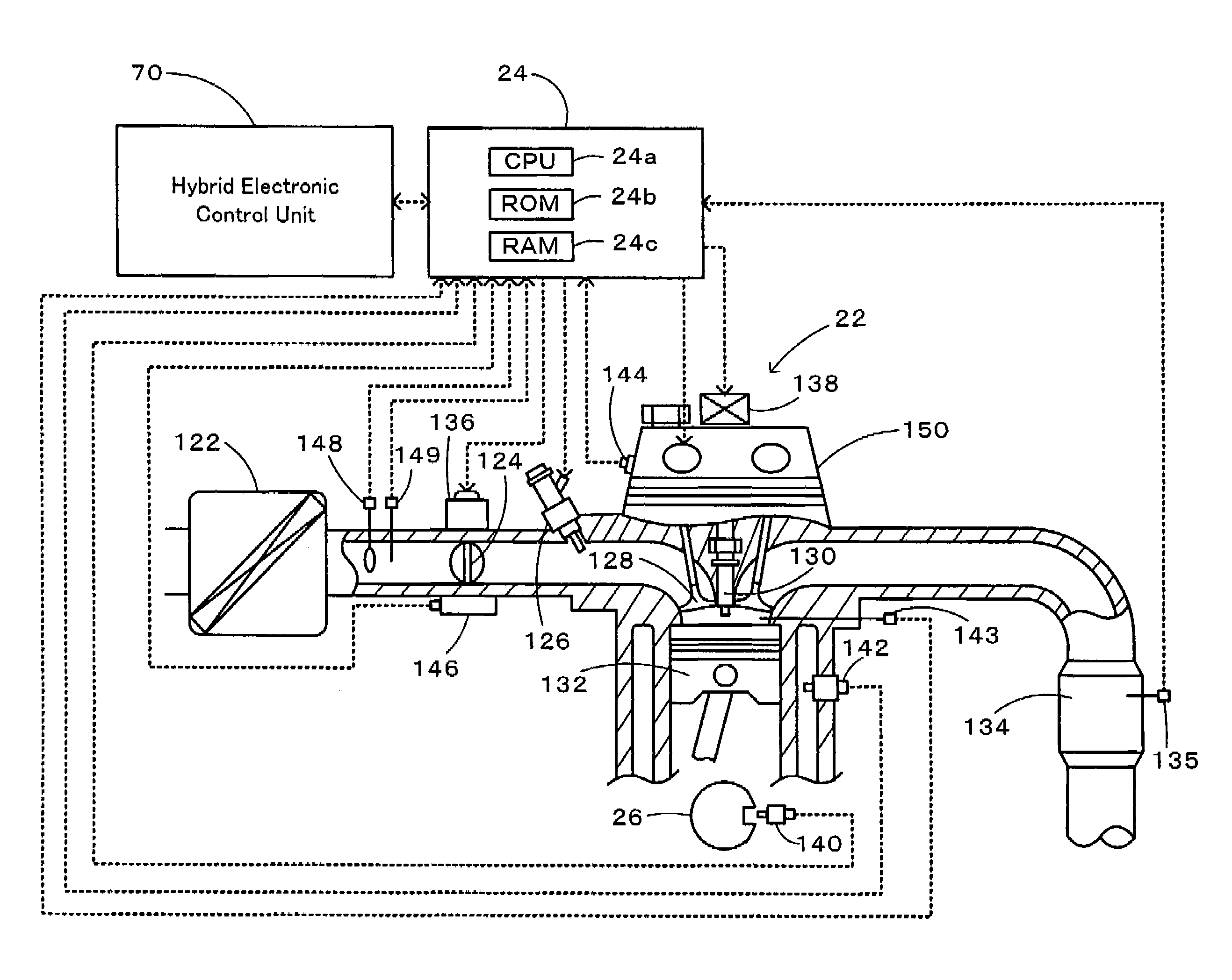
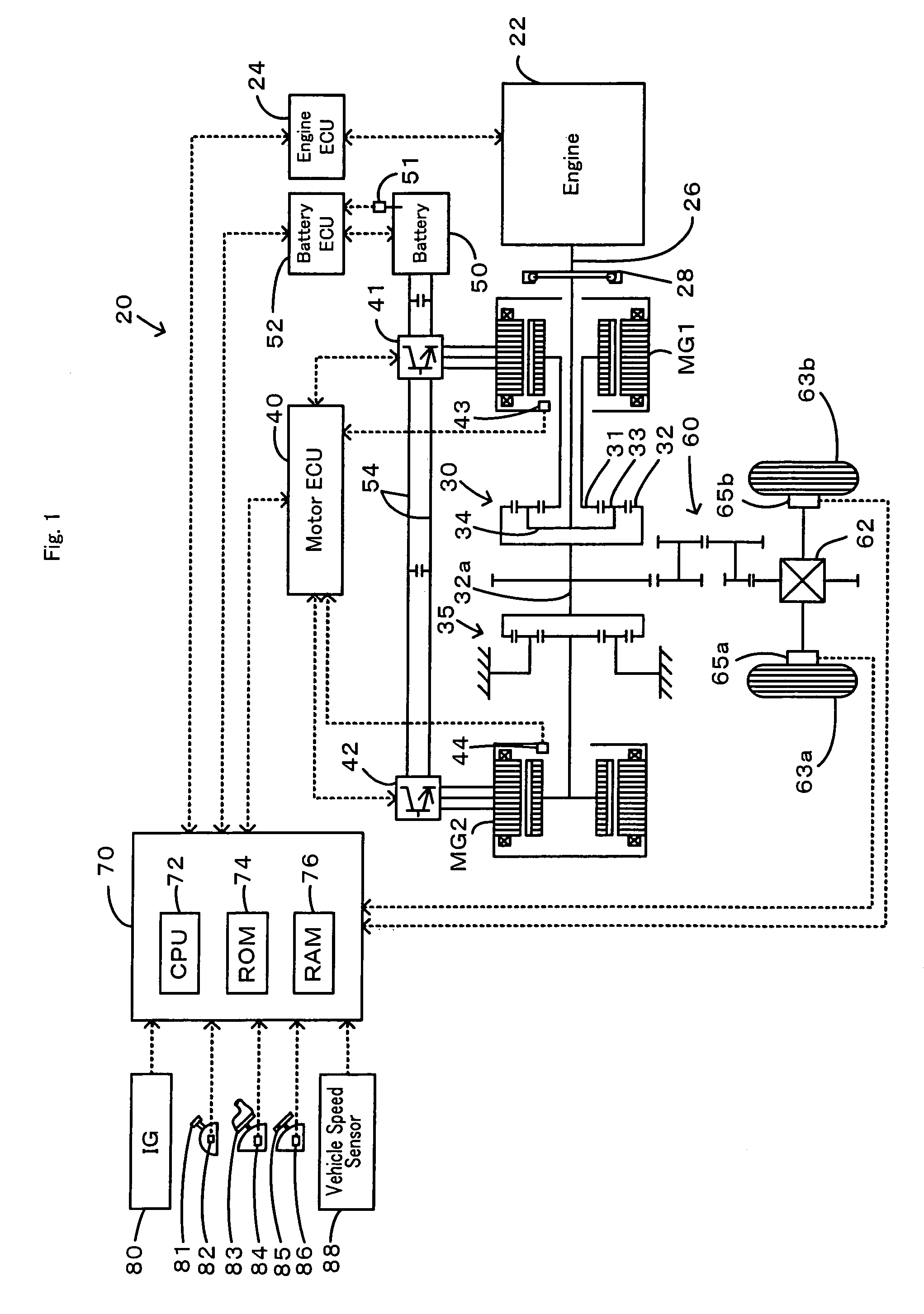
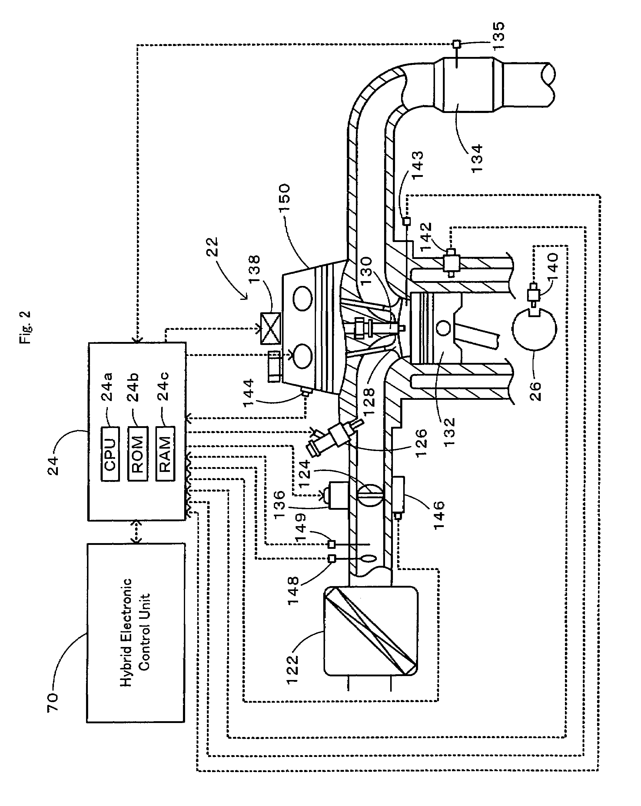
[0029]Some modes of carrying out the invention are described below as preferred embodiments with reference to the accompanied drawings. FIG. 1 schematically illustrates the configuration of a hybrid vehicle 20 equipped with a power output apparatus in the invention. As illustrated, the hybrid vehicle 20 of the embodiment includes an engine 22, a power distribution integration mechanism 30 as a planetary gear mechanism having its carrier 34 that rotates pinion gears 33 and is linked to a crankshaft 26 or an output shaft of the engine 22 via a damper 28, a motor MG1 that is linked to a sun gear 31 of the power distribution integration mechanism 30 and has power generation capability, a motor MG2 that is linked via a reduction gear 35 to a ring gear shaft 32a or a driveshaft connecting with a ring gear 32 of the power distribution integration mechanism 30, and a hybrid electronic control unit 70 that controls the operations of the whole hybrid vehicle 20. The ring gear shaft 32a or the...

second embodiment

[0050]In the hybrid vehicle 20 of the embodiment, in response to the driver's depression of the brake pedal 85 in requirement of the catalyst deterioration control with the catalyst deterioration control flag Fc set equal to 1, the torque command Tm1* of the motor MG1 is set to make the rotation speed Ne of the engine 22 approach to the target rotation speed Ne* in the state of continued combustion (firing) in the engine 22. The torque command Tm2* of the motor MG2 is then set in the range of the input limit Win of the battery 50. One possible modification may first set the torque command Tm2* of the motor MG2 in the range of the input limit Win of the battery 50 based on the braking torque demand Tr* and then set the torque command Tm1* of the motor MG1 to make the rotation speed Ne of the engine 22 approach to the target rotation speed Ne* in the state of continued combustion (firing) in the engine 22. In this modified braking control, when the torque command Tm2* of the motor MG2...


PUM


Abstract

In response to the driver's depression of a brake pedal in requirement of catalyst deterioration control with a catalyst deterioration control flag Fc set equal to 1, the braking control of the invention controls the operation of a motor to make a rotation speed Ne of an engine approach to a target rotation speed Ne* in a state of continued combustion (firing) of the engine (steps S180 and S190). Such control ensures a quick decrease of the rotation speed Ne of the engine to the target rotation speed Ne*, thus effectively reducing the wasteful fuel consumption due to the continued operation of the engine at a high rotation speed and enhancing the overall energy efficiency of the vehicle.

Description

TECHNICAL FIELD[0001]The present invention relates to a power output apparatus, a control method of the power output apparatus, and a vehicle equipped with the power output apparatus.BACKGROUND ART[0002]One proposed structure of a power output apparatus mounted on a vehicle has an internal combustion engine, a planetary gear unit that has a carrier and a ring gear respectively linked to an output shaft of the internal combustion engine and to an axle of the vehicle, a first motor that outputs power to a sun gear of the planetary gear unit, and a second motor that outputs power to the ring gear (see, for example, Patent Document 1). When the temperature of a catalyst in a catalytic converter used for exhaust emission control of the internal combustion engine increases or exceeds a preset reference temperature, this prior art power output apparatus prohibits cutoff of fuel to the internal combustion engine, with the view to restricting deterioration of the catalyst. In response to the...

Claims


Application Information

Patent Timeline
Patent Type & Authority Patents(United States)
IPC IPC(8): G06F19/00G05D1/00B60K6/44B60K6/445B60K6/448B60K6/52B60L50/16B60W10/06B60W10/08B60W20/00F01N3/24F02D29/02F02D41/04F02D45/00
CPCB60K6/40B60K6/445B60K6/448B60K6/52B60W10/06B60W10/08B60W20/00F02D29/02F02D41/12F02D41/123B60L11/123B60L11/14B60W20/1082B60K6/365B60K1/02Y02T10/6217F01N11/002F02D41/0235F16H2037/0866Y02T10/6243Y02T10/6265Y02T10/6286Y02T10/54Y02T10/6239Y02T10/7077B60W20/16B60L50/61B60L50/16Y02T10/40Y02T10/62Y02T10/7072Y02T10/70B60W20/15
Inventor KAMICHI, KENSUKEKIMURA, AKIHIROANDO, DAIGOMUTA, KOICHIRO
Owner TOYOTA JIDOSHA KK
Why Eureka
Try Eureka