Detection sensor

Inactive Publication Date: 2018-01-18
NAT UNIV CORP KYUSHU INST OF TECH (JP) +1
View PDF0 Cites 0 Cited by
  • Summary
  • Abstract
  • Description
  • Claims
  • Application Information

AI Technical Summary

Benefits of technology

[0015]As described above, in the example of the detection sensor reflecting one aspect of the present invention, the ratio of the intermediate tap in the second inductor is determined in accordance with the

Problems solved by technology

However, in the two-tuning detector circuit as shown in FIG. 1A, it is necessary to prepare two resonance circuits and arrange them properly, resulting in a complicated structure.
Further, in the Forster-Seeley detector circuit and the ratio detector circuit as shown in FIGS. 1B and 1C, respectively, an input circuit on their primary side and an output circuit on their secondary side are el

Method used


Image

  • Detection sensor
  • Detection sensor
  • Detection sensor

Examples


Example

First Embodiment

[0024]A detection sensor according to the Embodiment will be described with reference to FIG. 2 to FIG. 5C. The detection sensor according to the Embodiment is used as a human sensor that detects the presence or absence of a person, for example, and detects an object to be detected by detecting a frequency modulation of an oscillated signal. In other words, it is not intended to demodulate the signal by detecting an FM signal at a specific frequency, but it is intended to detect that frequency has been modulated. For this reason, in the Embodiment, a new technique that has not been used in the prior art, particularly in the configuration of an FM detector circuit, is used.

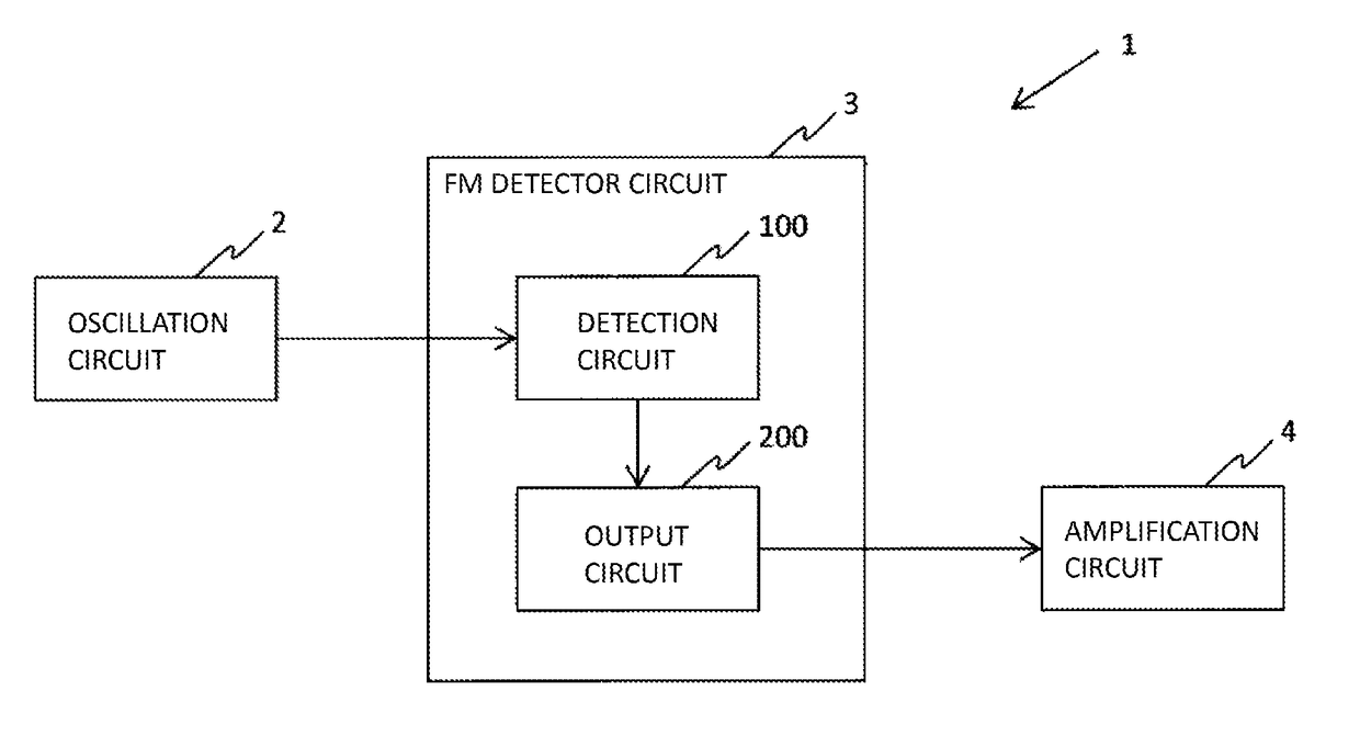
[0025]FIG. 2 is a functional block diagram of a detection sensor according to the Embodiment. A detection sensor 1 according to the Embodiment includes an oscillation circuit 2 that oscillates a signal of a predetermined frequency, an FM detector circuit 3 that detects an FM signal modulated by the ...


PUM


Abstract

Provided is a detection circuit that has a first inductor connected to two opened input ends and detects an external signal having a waveform with a gradient at each input end. The detection sensor further includes an output circuit that has a second inductor magnetically coupled with the first inductor as a primary side. In the output circuit, a third inductor constituting a delay circuit having one end connected to an intermediate tap of the second inductor is connected. Diodes are respectively connected to terminals of the second inductor in a forward direction. Other terminals of the diodes are connected to another terminal of the third inductor via elements each having an impedance characteristic. The output circuit outputs a detection signal detected at the input ends, from the other terminal(s) of at least one of the diodes.

Description

CROSS REFERENCE TO RELATED APPLICATIONS[0001]This application is a continuation-in-part of International Patent Application No. PCT / JP2016 / 057661, filed on Mar. 10, 2016, the disclosure of which including the specification, drawings and abstract is incorporated herein by reference in its entirety. International Patent Application No. PCT / JP2016 / 057661 is entitled to and claims the benefit of Japanese Patent Application No. 2015-064418, filed on Mar. 26, 2015, the disclosure of which including the specification, drawings and abstract is incorporated herein by reference in its entirety.BACKGROUNDTechnological Field[0002]The present invention relates to a detection sensor using a detector circuit for detecting a frequency modulated signal.Description of Related Art[0003]Several systems are generally known as a frequency modulation (hereinafter referred to as FM) detector circuit for detecting a frequency modulated signal. FIGS. 1A to 1C are diagrams showing FM detector circuits in the ...

Claims


Application Information

Patent Timeline
IPC IPC(8): G01V3/08G01R23/12
CPCG01V3/088G01R23/12H03D3/10
Inventor SATO, YASUSHI
Owner NAT UNIV CORP KYUSHU INST OF TECH (JP)
Why Eureka
Try Eureka