Magnetically immune gatedriver circuit

a gatedriver and magnetic immunity technology, applied in the field of power converter control circuits, can solve problems such as cross-conduction of igbt and control function errors

Active Publication Date: 2022-11-15
VESTAS WIND SYST AS
View PDF15 Cites 0 Cited by
  • Summary
  • Abstract
  • Description
  • Claims
  • Application Information

AI Technical Summary

Benefits of technology

[0011]Such gatedriver circuit is advantageous, since it allows galvanic separation which is highly immune towards strong magnetic fields which may disturb signal transfer using a traditional transformer. By the use of two separate cores and the opposite winding directions, the influence of magnetic fields on the control signal can be eliminated or at least significantly reduced, thereby allow the gatedriver circuit to function also in environments with strong magnetic fields.
[0026]In a third aspect, the invention provides a wind turbine comprising a gatedriver circuit according to the first aspect, or an electric power converter according to the second aspect. Especially, the wind turbine may comprise a power converter comprising an IGBT module, and wherein the gatedriver circuit is arranged to control switching of the IGBT module. Especially, the wind turbine may comprise an electric power generator arranged to generate an electric power of at least 1 MW, such as 2-10 MW or more. In such MW wind turbines, the gatedriver circuit and thus also the galvanic separation, is present close to the switching currents of thousands of amperes, and thus for such size wind turbines, the gatedriver circuit according to the invention can significantly improve the quality of the transferred control signals.

Problems solved by technology

This will lead to a wrong signal level transfer over the galvanic barrier of the gatedriver, thus distorting the control signals, which again may cause errors in the control function of the power electronic switches of the converter.
In worst case scenarios this may lead to a cross conduction of the IGBT, if there is no other systems in place to secure this cannot happen, on the high voltage side of the gatedriver.

Method used


Image

  • Magnetically immune gatedriver circuit
  • Magnetically immune gatedriver circuit
  • Magnetically immune gatedriver circuit

Examples


Embodiment Construction

[0043]The gatedriver circuit according to the invention is advantageous for wind turbines, e.g. wind turbines capable of generating high electric power such as more than 1 MW. However, it is to be understood that the invention may be other power electric applications, especially where operation of power electronic switches are controlled by control signals in an environment involving strong magnetic fields.

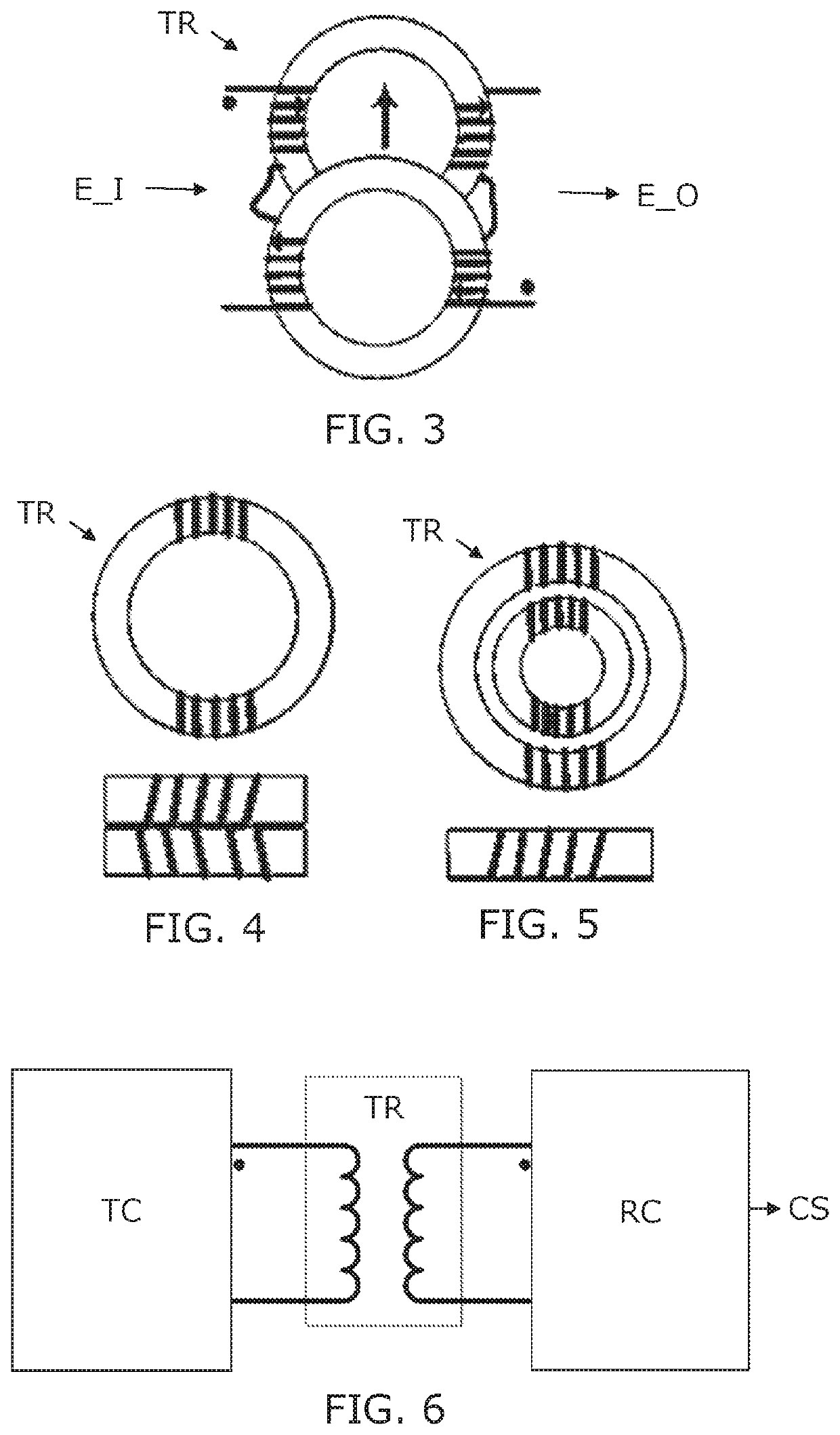
[0044]FIG. 1 illustrates a wind turbine with three rotor blades for driving an electric generator located inside the nacelle on top of a tower. Typically, the electric power converter in a wind turbine can be placed up-tower or down tower. The full scale converter typically comprises a power stack for AC / DC conversion and a power stack for DC / AC conversion. Furthermore the converter system comprises reactors, filter capacitors, breakers, busbars and other converter related systems. The gatedriver circuit with the galvanic separation transformer according to the invention will norm...


PUM

PropertyMeasurementUnit
frequencyaaaaaaaaaa
switching frequenciesaaaaaaaaaa
outer diameteraaaaaaaaaa

Abstract

A gatedriver circuit for controlling a power electronic switch. The circuit provides a galvanic separation and is magnetically immune. The gatedriver circuit comprises a transformer arranged with two separate cores of magnetically conductive material each forming a closed loop. A first electrical conductor has windings around a part of both cores, and a second electrical conductor also has windings around part of both cores. The two cores are positioned close to each other to allow mutual magnetic interaction. The windings of the first and second electrical conductors around the first core have the same winding direction, and the windings of the first and second electrical conductors around the second core have opposite winding direction of the windings of the first and second electrical conductors around the first core, so as to counteract electric influence induced by a common magnetic field through the closed loops of the first and second cores. Hereby, such gatedriver circuit is suitable for controlling power switches in environments with strong magnetic fields, e.g. inside a high power wind turbine.

Description

FIELD OF THE INVENTION[0001]The present invention relates to the field of power converters, more specifically for circuits for control of power converters e.g. in wind turbines.BACKGROUND OF THE INVENTION[0002]Electric control signals for control of power switching circuits, gatedrive circuits, e.g. in a wind turbine, is normally transferred via galvanic separation means. The signals can e.g. be transferred via a traditional 1:1 electric transformer to provide galvanic separation. Such transformer will normally be located inside the converter cabinet, and thus inside the power stack where it is a part of the gatedriver, driving an IGBT module.[0003]In a wind turbine with an electric power of several MW, the environment inside the converter cabinet is influence by a strong magnetic radiation due to large currents running through the busbars, generating a surrounding magnetic field. There will also be stray magnetic fields around reactors in the converter, and finally EMI is generated...

Claims


Application Information

Patent Timeline
Patent Type & Authority Patents(United States)
IPC IPC(8): H01F17/04H01F27/34H01F27/32H01F17/06H01F27/24H01F19/08H03K17/16H01F27/38H03K17/691H01F38/00
CPCH01F27/34H01F17/06H01F19/08H01F27/24H01F27/323H01F27/38H03K17/168H03K17/691H01F2019/085H01F2038/006Y02E10/76
Inventor PALLESGAARD, STIG LUND
Owner VESTAS WIND SYST AS
Why Eureka
Try Eureka