Magnetically immune gatedriver circuit

a gatedriver and magnetic immunity technology, applied in the field of magnetic immunity gatedriver circuits, can solve problems such as cross-conduction of igbt and errors in control functions, and achieve the effects of eliminating or at least significantly reducing the influence of magnetic fields on the control signal, high immunity to strong magnetic fields, and galvanic separation

US20190103217A1Active Publication Date: 2019-04-04VESTAS WIND SYST AS
0 Cites 1 Cited by

Patent Information

Authority / Receiving Office
US · United States
Current Assignee / Owner
Publication Date
2019-04-04

Smart Images

  • Figure 1
    Figure 1
  • Figure 2
    Figure 2
  • Figure 3
    Figure 3
Patent Text Reader

Abstract

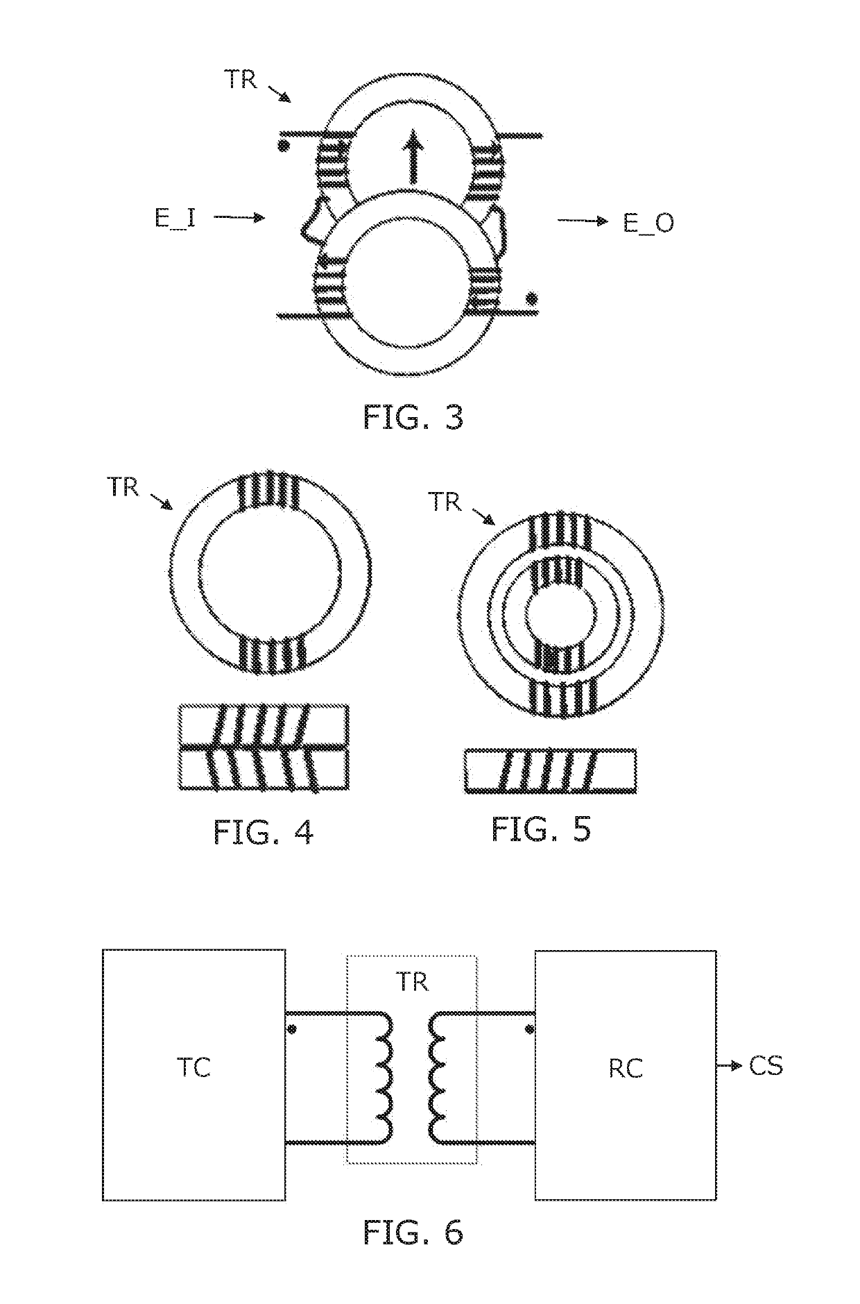
A gatedriver circuit for controlling a power electronic switch. The circuit provides a galvanic separation and is magnetically immune. The gatedriver circuit comprises a transformer arranged with two separate cores of magnetically conductive material each forming a closed loop. A first electrical conductor has windings around a part of both cores, and a second electrical conductor also has windings around part of both cores. The two cores are positioned close to each other to allow mutual magnetic interaction. The windings of the first and second electrical conductors around the first core have the same winding direction, and the windings of the first and second electrical conductors around the second core have opposite winding direction of the windings of the first and second electrical conductors around the first core, so as to counteract electric influence induced by a common magnetic field through the closed loops of the first and second cores. Hereby, such gatedriver circuit is suitable for controlling power switches in environments with strong magnetic fields, e.g. inside a high power wind turbine.
Need to check novelty before this filing date? Find Prior Art

Description

FIELD OF THE INVENTION

[0001] The present invention relates to the field of power converters, more specifically for circuits for control of power converters e.g. in wind turbines.BACKGROUND OF THE INVENTION

[0002] Electric control signals for control of power switching circuits, gatedrive circuits, e.g. in a wind turbine, is normally transferred via galvanic separation means. The signals can e.g. be transferred via a traditional 1:1 electric transformer to provide galvanic separation. Such transformer will normally be located inside the converter cabinet, and thus inside the power stack where it is a part of the gatedriver, driving an IGBT module.

[0003] In a wind turbine with an electric power of several MW, the environment inside the converter cabinet is influence by a strong magnetic radiation due to large currents running through the busbars, generating a surrounding magnetic field. There will also be stray magnetic fields around reactors in the converter, and finally EMI is generated...

Examples

Embodiment Construction

[0043]The gatedriver circuit according to the invention is advantageous for wind turbines, e.g. wind turbines capable of generating high electric power such as more than 1 MW. However, it is to be understood that the invention may be other power electric applications, especially where operation of power electronic switches are controlled by control signals in an environment involving strong magnetic fields.

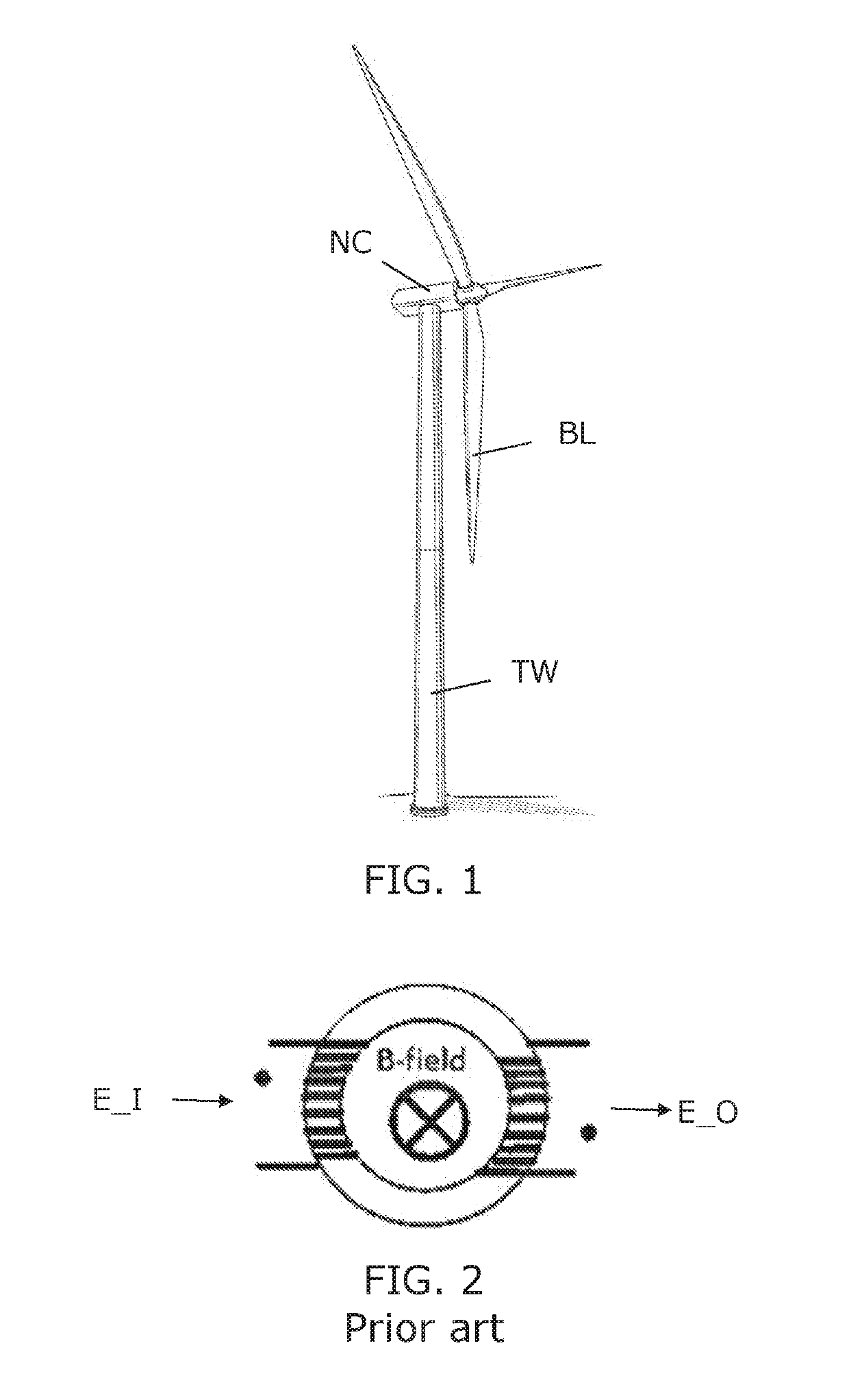
[0044]FIG. 1 illustrates a wind turbine with three rotor blades for driving an electric generator located inside the nacelle on top of a tower. Typically, the electric power converter in a wind turbine can be placed up-tower or down tower. The full scale converter typically comprises a power stack for AC / DC conversion and a power stack for DC / AC conversion. Furthermore the converter system comprises reactors, filter capacitors, breakers, busbars and other converter related systems. The gatedriver circuit with the galvanic separation transformer according to the invention will norm...