Connector

Active Publication Date: 2019-01-17
IRISO ELECTRONICS CO LTD
View PDF9 Cites 6 Cited by
  • Summary
  • Abstract
  • Description
  • Claims
  • Application Information

AI Technical Summary

Benefits of technology

The present invention is a connector that has a surface that guides the insertion of the connection target object into the insertion port. This surface ensures that even if the connection target object is inserted at a different position, it will still guide it to the correct position in the fitting chamber. This makes it easier to insert the connection target object and reduces the size of the connector.

Problems solved by technology

However, the smaller a connector is, the more difficult the fitting operation is, because the opening of an insertion port through which a connection target object is inserted into a fitting chamber of the housing of the connector also has a smaller area.
For example, the smaller a connector for substrate-to-substrate connection is, such as that shown in FIG. 1 of Japanese Patent Laid-Open No. 2016-129148, the more difficult the fitting operation is.
Therefore, conventionally, in the case of the connector for substrate-to-substrate connection, it is difficult to align the socket connector and the plug connector with each other for fitting connection, resulting in inefficient operation, and further causing a possibility of breakage of the connectors if the fitting operation is performed in a haste forcible manner.
The difficulty in the fitting operation is not specific to a connector for substrate-to-substrate connection but common to a connector that requires fitting operation of inserting a connection target object into a fitting chamber via an insertion port of the housing of the connector.
Because the smaller the area of the opening of the insertion port due to the reduction in size of the connector is, the more difficult the alignment of the connection target object with the insertion port is, even though fitting operation is performed in a state in which the connector and the connection target object are visually recognizable.

Method used


Image

  • Connector
  • Connector
  • Connector

Examples


Embodiment Construction

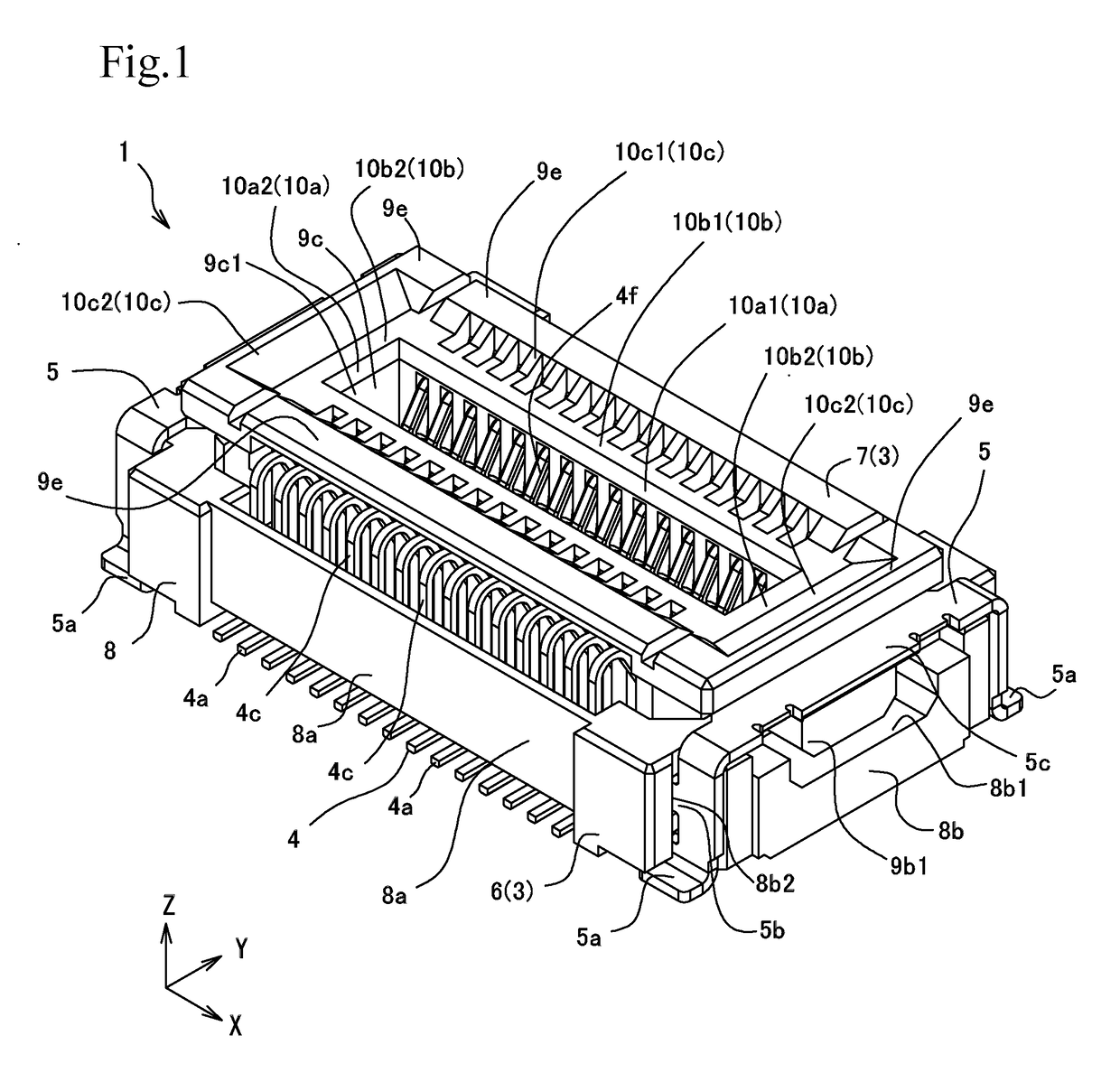
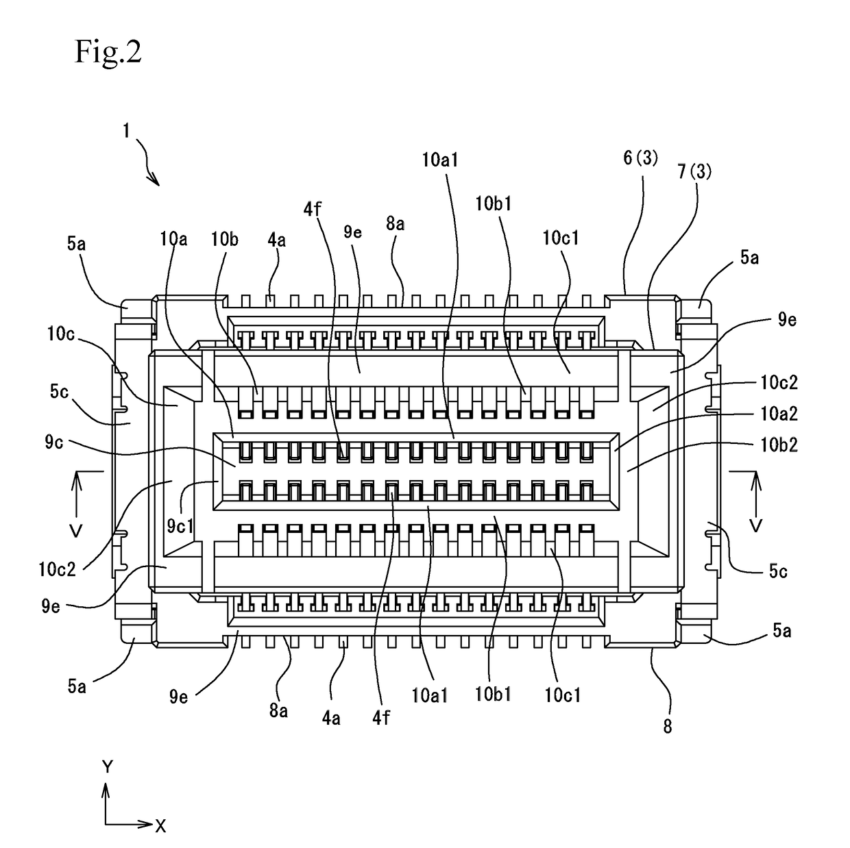
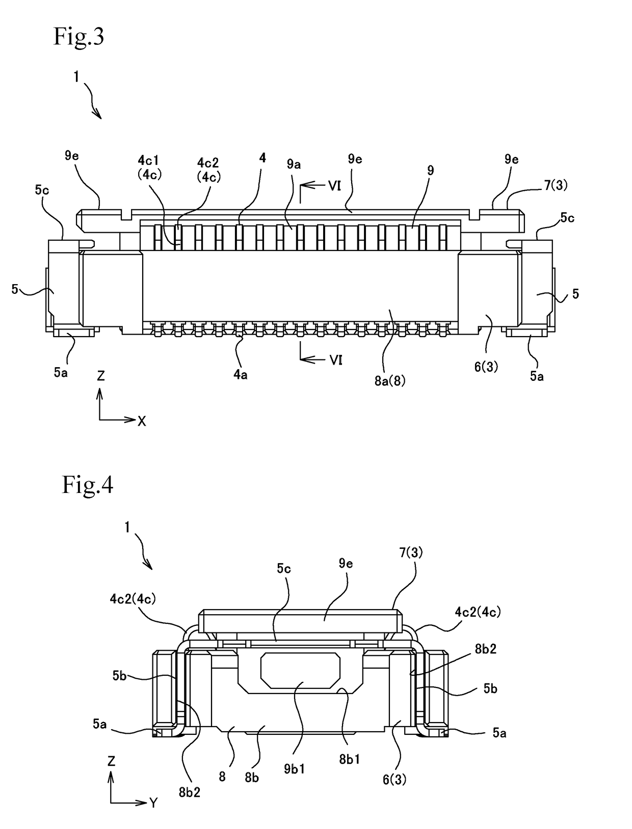
[0052]An embodiment of a connector according to the present invention will be described below with reference to the drawings. In the following embodiment, the connector according to the present invention is a socket connector 1, which is a connector for substrate-to-substrate connection and has the floating function, but it is not necessarily restricted to the above.

[0053]The terms “first” and “second” described in the present specification and claims are intended to distinguish components in different inventions and embodiments but are not intended to show a specific order or superiority / inferiority. Further, in the description of the present specification and claims, the width direction or the rightward / leftward direction of the socket connector 1 is a direction X, the depth direction or the frontward / rearward direction thereof is a direction Y, and the height direction or the upward / downward direction thereof is a direction Z for ease of description, but the definition of the dir...


PUM


Abstract

A connector to which a connection target object is fitted and connected by inserting the connection target object into a fitting chamber is configured to allow the fitting operation to be readily performed even in a case where the connector is small.An insertion guiding surface is provided round an insertion port through which the connection target object is inserted. The insertion guiding surface has an inner guiding surface that extends from the edge of the insertion port toward the fitting chamber, an intermediate guiding surface provided in a region outside the inner guiding surface, and an outer guiding surface provided in a region outside the intermediate guiding surface. The inner guiding surface differs from the intermediate guiding surface in terms of shape, and the intermediate guiding surface differs from the outer guiding surface in terms of shape.

Description

BACKGROUND OF THE INVENTION[0001]Field of the Invention[0002]The present invention relates to a connector into which a connection target object is so inserted that the connection target object is fitted and connected to the connector.[0003]Description of the Related Art[0004]As the size of an electric apparatus further decreases, a connector is also required to be reduced in size. However, the smaller a connector is, the more difficult the fitting operation is, because the opening of an insertion port through which a connection target object is inserted into a fitting chamber of the housing of the connector also has a smaller area. For example, the smaller a connector for substrate-to-substrate connection is, such as that shown in FIG. 1 of Japanese Patent Laid-Open No. 2016-129148, the more difficult the fitting operation is.[0005]That is, the problem described above will be described with reference to a socket connector and a plug connector that form a connector for substrate-to-s...

Claims


Application Information

Patent Timeline
IPC IPC(8): H01R12/71H01R12/55H01R12/70H01R12/52
CPCH01R12/7005H01R12/73H01R12/91H01R12/52H01R12/55H01R12/7064H01R12/7076H01R12/7082H01R12/716
Inventor SUZUKI, HITOSHIOHKUMA, YOSHIHITOYUKUTAKE, HIROAKI
Owner IRISO ELECTRONICS CO LTD
Why Eureka
Try Eureka