

Imaging lens and imaging apparatus
- Summary
- Abstract
- Description
- Claims
- Application Information
AI Technical Summary
Benefits of technology
Problems solved by technology
Method used
Image

Examples
first embodiment
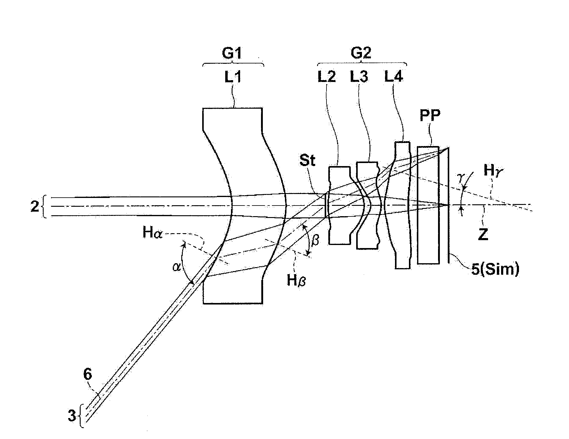
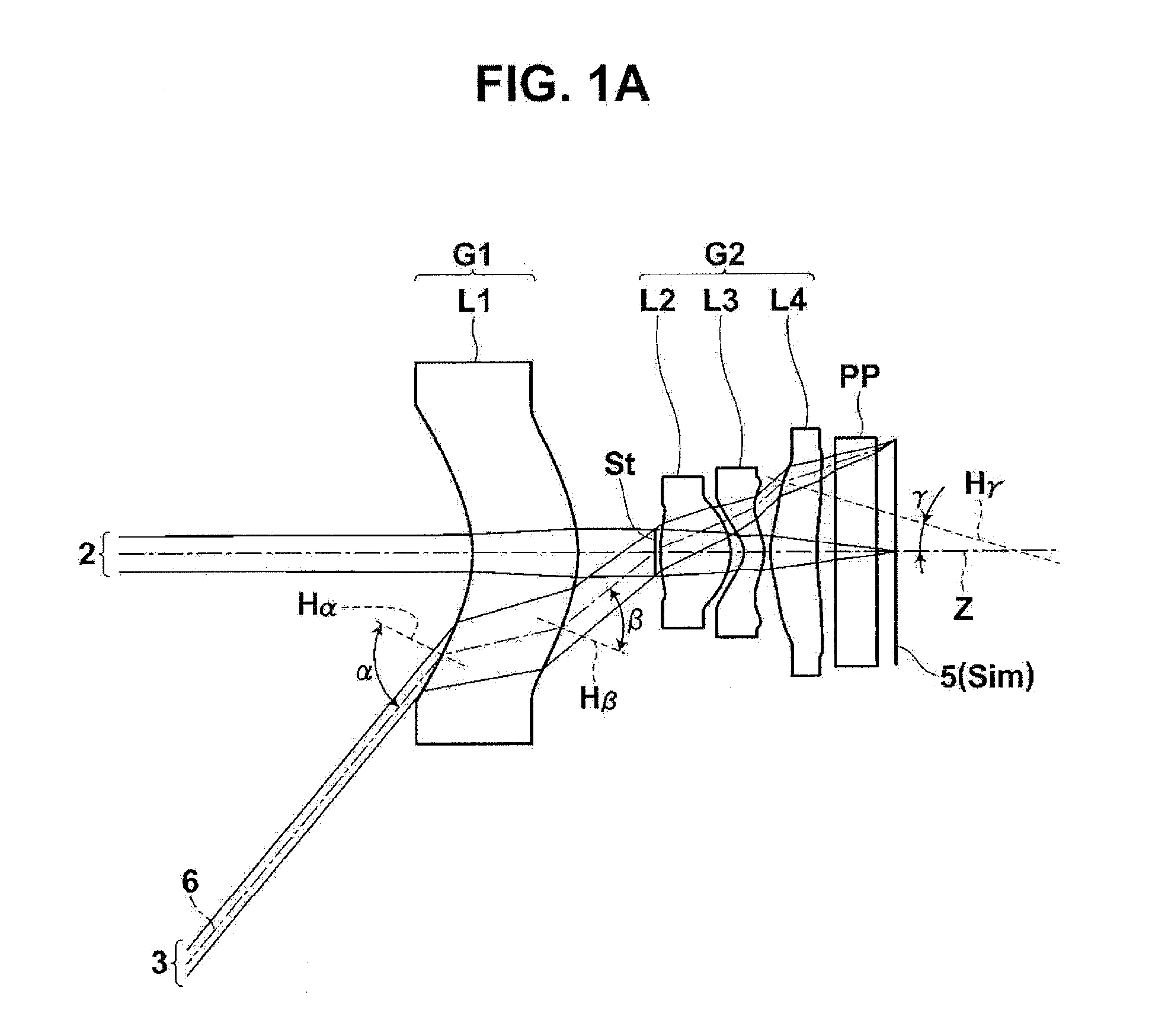
[0074]As shown in FIG. 1A, the imaging lens according to the invention includes a first lens L1 with a meniscus shape having a concave surface facing the object side, a second positive lens L2, a third negative lens L3 with a meniscus shape having a convex surface facing the image side, and a fourth lens L4 having a convex surface facing the object side which are arranged in this order from the object side along the optical axis Z. In order to reduce the size of the imaging lens, it is preferable to form the imaging lens with a small number of lenses. It is preferable that the number of lenses be 4 as in the example shown in FIG. 1A. The imaging lens shown in FIG. 1A further includes an aperture diaphragm St provided between the first lens L1 and the second lens L2. FIG. 1A does not necessarily show the shape or size of the aperture diaphragm St, but shows the position of the aperture diaphragm St on the optical axis Z.
[0075]When the object-side surface of the first lens L1 has a co...
second embodiment
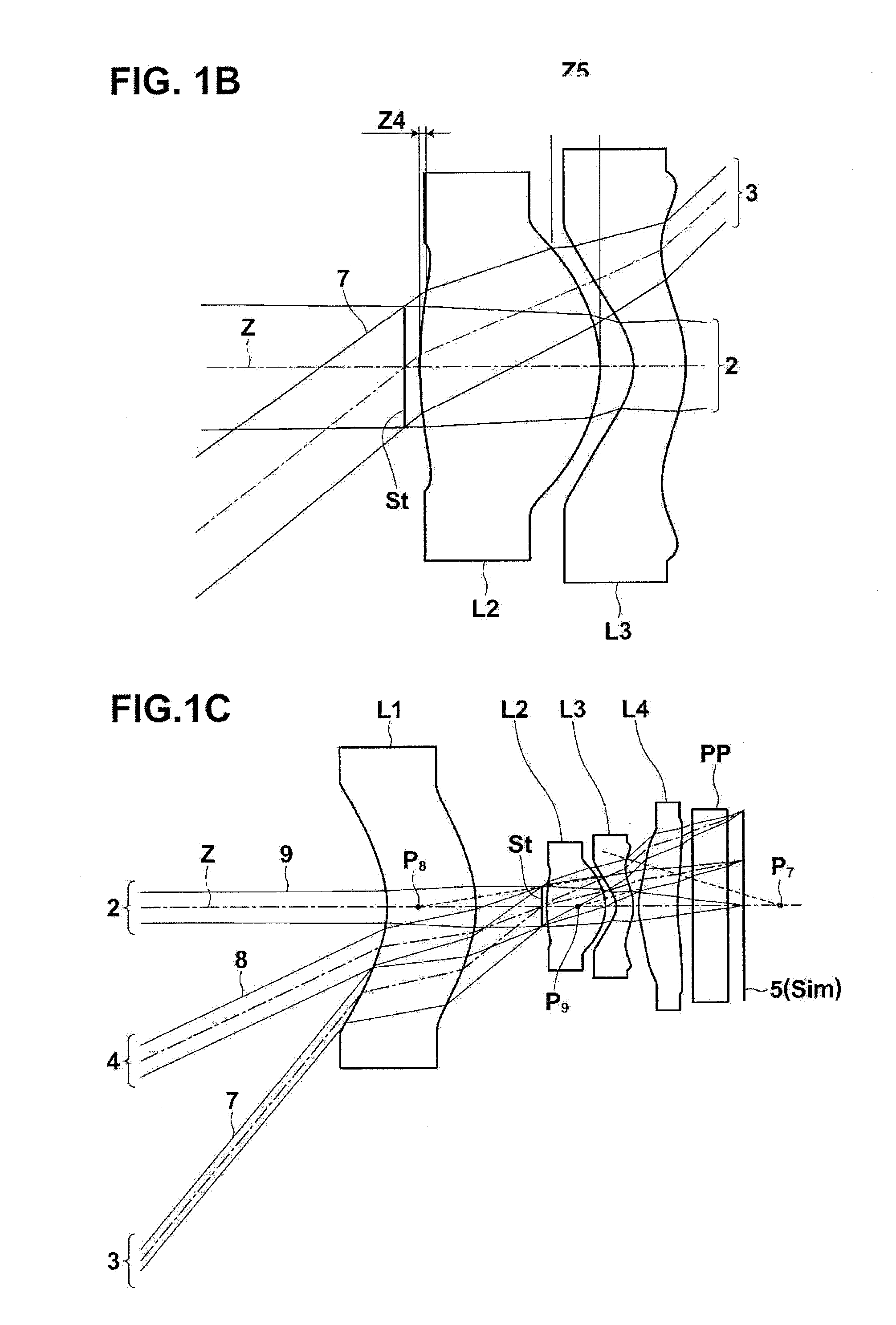
[0128]As shown in FIG. 2B, the imaging lens according to the invention is configured such that a normal line H2f of the object side-surface of the second lens L2 at a point where the outermost light beam 9 of the on-axis light flux 2 passes intersects the optical axis Z at a position closer to the object side than the object side-surface. In FIG. 2B, an intersection point P2f between the normal line H2f and optical axis Z is arranged closer to the object side than the object side-surface of the second lens L2. FIG. 2B is an enlarged view illustrating a main part of the imaging lens shown in FIG.2A including the aperture diaphragm St, the second lens L2, and the on-axis light flux 2. In FIG. 2B, the light flux 3 at the maximum angle of view and an object-side light flux on the left side of a break line are not shown.
[0129]When the structure in which the intersection point P2f between the normal line H2f and optical axis Z is arranged closer to the object side than the object side-sur...
third embodiment
[0136]When the distance between the first lens L1 and the second lens L2 on the optical axis is D and the focal length of the entire system is f, it is preferable that the imaging lens according to the invention satisfy the following Conditional expression 1:
0.25<D / f<4.0 [Conditional expression 1]
[0137]The operation and effect obtained when Conditional expression 1 is satisfied are the same as those of the first embodiment.
[0138]The imaging lens according to the third embodiment of the invention may have one or any combination of the preferred structures or the adopted structures of the imaging lens according to the first embodiment within the range in which the above-mentioned basic structure of this embodiment is consistent with that of the first embodiment.
[0139]For example, as shown in FIGS. 1A and 2A, the second lens group G2 of the imaging lens according to the third embodiment of the invention may be configured so as to include a second positive lens L2, a third negati...
PUM
 Abstract
Description
Claims
Application Information