Image Capturing Apparatus

Inactive Publication Date: 2008-03-20
MITSUBISHI ELECTRIC CORP
View PDF2 Cites 59 Cited by
  • Summary
  • Abstract
  • Description
  • Claims
  • Application Information

AI Technical Summary

Benefits of technology

[0008] The present invention has been made to solve the above-described various problems, and has an object to obtain a three axis lens shifting mechanism capable of achie

Problems solved by technology

The above-described conventional objective lens drive unit is unsuitable for size reduction since a magnetic circuit for obtaining the electromagnetic force in the direction of the optical axis and a magnetic circuit for obtaining the electromagnetic force in the direction of rotation about the support shaft are provided separately.
Further, another pair of magnetic circuits are additionally required in the case of forming a three axis lens shifting mechanism for implementing an image blur correcting function and an automatic focu

Method used


Image

  • Image Capturing Apparatus
  • Image Capturing Apparatus
  • Image Capturing Apparatus

Examples


first embodiment

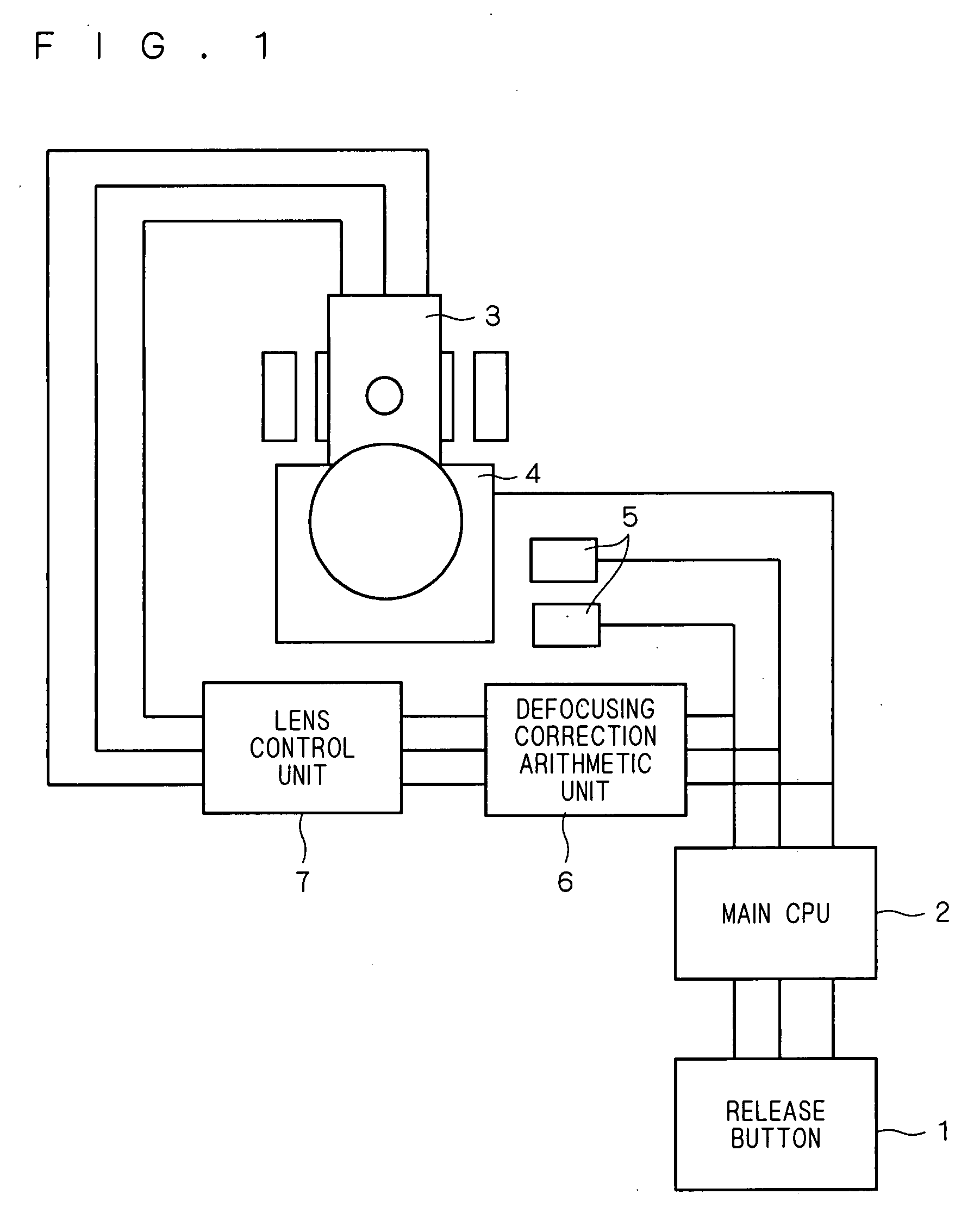
[0035]FIG. 2 is a disassembled perspective view showing the structure of a main part of an image capturing apparatus according to the present embodiment, namely, the structure of a mechanism mainly composed of the three axis lens shifting mechanism 3.

[0036] In FIG. 2, a lens group 8 forming an objective lens (image forming lens) is formed of one or a plurality of lenses (not shown), and the one or plurality of lenses are held by a lens holder having a screw-threaded cylindrical contour with a predetermined space kept therebetween. A first movable base 9, as shown in FIG. 2, is made up of a substantially cylindrical portion for holding the objective lens and a projecting portion 9p holding a pair of coils to be described later and projecting from the cylindrical portion in the first direction X, and the lens group 8 is threadingly held in a screw hole 9a. Further, an interference avoiding hole 9b having a rectangular shape in transverse cross section is formed to extend through the ...

second embodiment

[0069]FIG. 7 is a disassembled perspective view showing the structure of a main part of an image capturing apparatus according to the present embodiment, and corresponds to FIG. 2. In FIG. 7, members equal to or corresponding to those of FIG. 2 are indicated by the same reference characters.

[0070] The difference of the structure of the image capturing apparatus according to the present embodiment from the first embodiment will now be described.

[0071] In the first embodiment, the yoke 18, support shaft 19 and pair of magnets 20 are disposed in the fixed part 23 (cf. FIG. 2); in the present embodiment, however, these components 18, 19 and 20 are all disposed in the second movable part 17. In the first embodiment, the plate springs 15 are used to connect and fix the first movable part 11 and second movable part 17; in the present embodiment, however, the plate springs 15 are used as members for connecting and fixing the fixed part 23 and second movable part 17 to each other. Further,...

third embodiment

[0076]FIG. 8 is a disassembled perspective view showing the structure of a main part of an image capturing apparatus according to the present embodiment, and relates to an improvement of the structure shown in FIG. 7 described in the second embodiment. In FIG. 8, the focusing coil 14 and magnetic pieces 13 provided thereon are practically disposed to be encased within the projecting portion 9p of the first movable base 9 to constitute part of members of the first movable part 11. FIG. 9 is a top view showing the positional relationship between the magnetic pieces 13 and magnets 20 (or magnetic circuit formed by the yoke 18 and magnets 20) with no load (in the condition where no current flows through the pair of coils 10a and 10b for handshake correction), and one of the tables shown in FIG. 9 indicates the direction of electromagnetic force generated when flowing current to the active side 10be (cf. FIG. 2) of the coil 10b positioned above of the pair of coils 10a and 10b from the n...


PUM


Abstract

The present invention belongs to the field of an image capturing apparatus such as a camera for mobile phone and the like, and has an object to obtain a three axis lens shifting mechanism capable of achieving size reduction and cost reduction with simple structure and an image capturing apparatus equipped with such three axis lens shifting mechanism. A single magnetic circuit exerts an influence of a magnetic field produced by magnets (20) upon active sides of a focusing coil (14) and active sides of coils (10a), (10b). Therefore, movable parts (11+17) can be driven in the direction of optical axis (Z) only by controlling the direction of energizing the focusing coil (14), and further, a first movable part (11) can be driven in a first direction (X) or second direction (direction of rotation) (Y) only by combination of the directions of energizing the coils (10a), (10b). This allows the sharing of the magnetic circuit and an electromagnetic actuator.

Description

TECHNICAL FIELD [0001] The present invention belongs to the field of an image capturing apparatus such as a still camera, a video camera, a camera for mobile phone and the like, and more specifically, it relates to the structure of a three axis lens shifting mechanism (shake correcting device) for correcting a blurred image caused by user's handshake or the like and an image capturing apparatus equipped with such three axis lens shifting mechanism. BACKGROUND ART [0002] A conventional objective lens drive unit adjusts the position of the objective lens in the direction of focusing by sliding a lens holder (objective lens) inserted in a support shaft in the direction of the optical axis and along the support shaft by means of an electromagnetic force obtained by the interaction between current which energizes a focusing coil and a magnetic field, and also adjusts the position of the objective lens in the direction of tracking by rotating the lens holder about the support shaft by mea...

Claims


Application Information

Patent Timeline
IPC IPC(8): H04N5/225
CPCG02B7/023G02B7/08H04N5/2254G03B3/10G03B3/02H04N23/55G03B5/04G03B13/34G03B2205/0069
Inventor WATANABE, NORIHIROKOMORI, NORIYUKIMICHIMORI, ATSUSHIKUNISHIO, HIDEKI
Owner MITSUBISHI ELECTRIC CORP
Why Eureka
Try Eureka