Control device for hybrid vehicle driving device, and control method for the driving device

Active Publication Date: 2008-09-25
TOYOTA JIDOSHA KK
View PDF4 Cites 61 Cited by
  • Summary
  • Abstract
  • Description
  • Claims
  • Application Information

AI Technical Summary

Benefits of technology

[0019]A portion of the power transmission device may be a differential mechanism that has a first element linked to an engine as the internal combustion engine, and a second element linked to a first electric motor, and a third element linked to a transmission member and a second electric motor as the electric motor, and may distribute output of the engine to the first electric motor and the transmission member. This allows construction of a power transmission device that is capable of causing the motor-powered travel of the hybrid vehicle and causing the differential mechanism to function as a transmission even if operation oil for executing the shift is not supplied.
[0020]Furthermore, the differential mechanism may be constructed of a planetary gear device, and the first element may be a carrier of the planetary gear device, and the second element may be a sun gear of the planetary gear device,

Problems solved by technology

However, since the oil pump linked to the output shaft of the engine is not rotationally driven during the motor-powered travel during which the rotational driving of the engine is stopped, there is a possibility that during the motor-powered travel, necessary supply of lubrication oil to various portions of the power transmission devices may fail and therefore rotating members, such as gears and the like, may undergo seizure or the like and therefore decline in durability.
For example, if it may be possible to supply lubrication oil to various portions of the power transmission devices by the well-known differential ring gear or the like splashing up lubrication oil accumulated in the power transmission devices, lubrication can be accomplished, for example, on the meshing portions of tooth surfaces of gears and the like, but there is a possibility of failure of sufficient supply of lubrication oil to interiors

Method used


Image

  • Control device for hybrid vehicle driving device, and control method for the driving device
  • Control device for hybrid vehicle driving device, and control method for the driving device
  • Control device for hybrid vehicle driving device, and control method for the driving device

Examples


Example

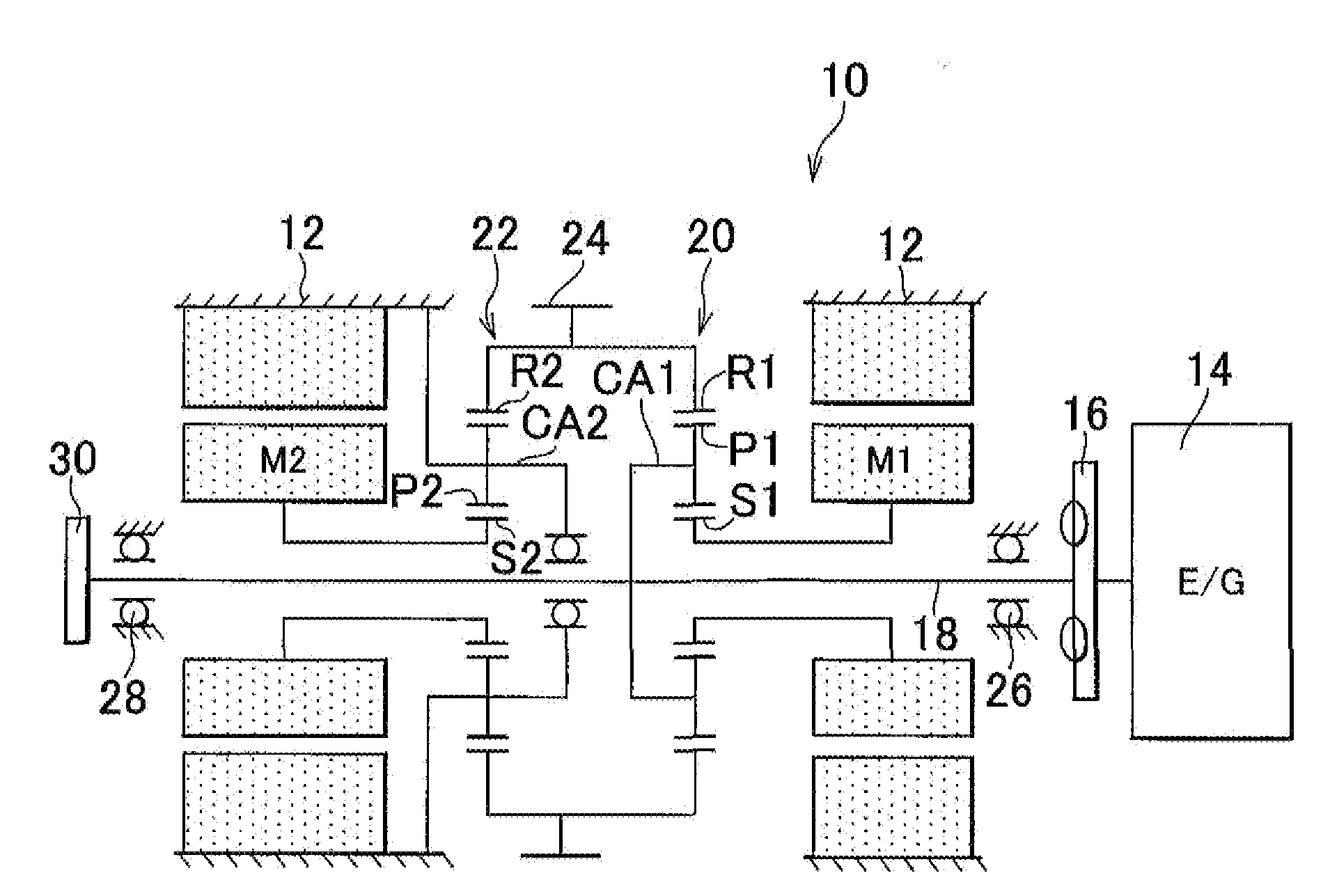
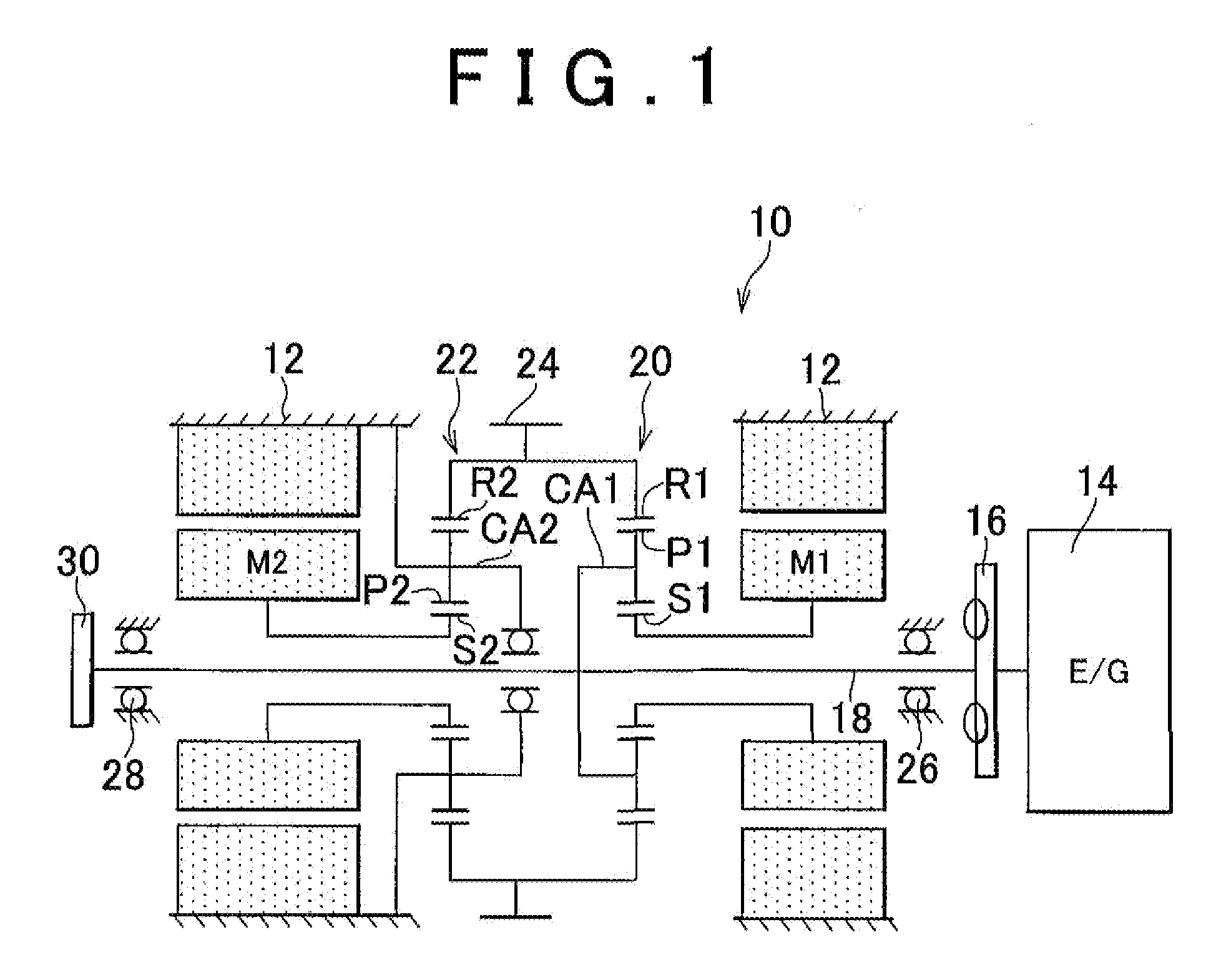
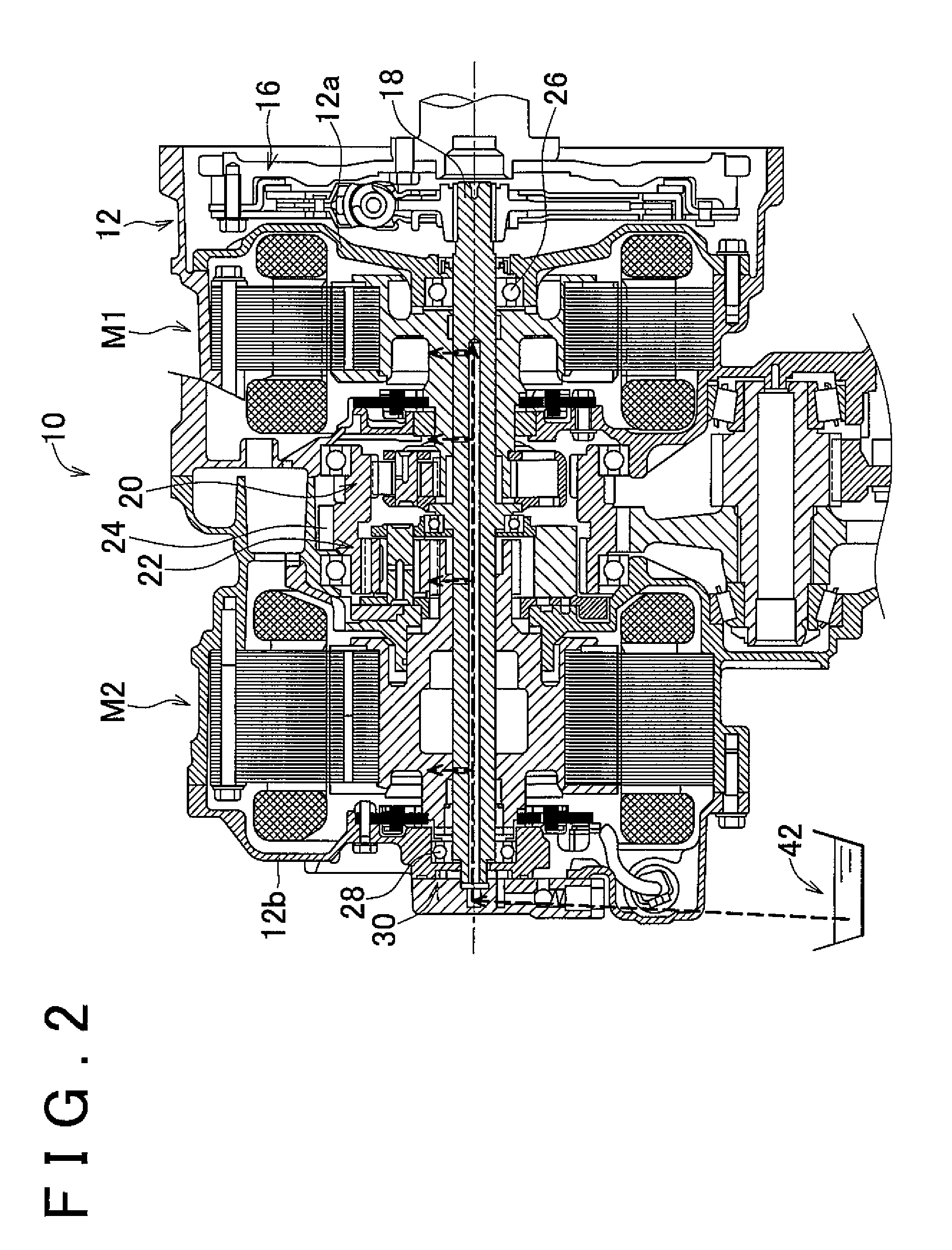
[0041]A first embodiment of the invention will be described. FIG. 1 is a skeleton diagram illustrating a speed change mechanism 10 as a power transmission device that constitutes a portion of a driving device of a hybrid vehicle in various embodiments of the invention. In FIG. 1, the speed change mechanism 10 has, within a transaxle (T / A) case 12 (hereinafter, referred to as the case 12), a damper 16 which is operatively linked to an output shaft (e.g., the crankshaft) of an engine 14 that is an internal combustion engine, for example, a gasoline engine, a diesel engine, etc., as a vehicle travel-purpose drive force source, and which absorbs the pulsations from the engine 14 caused by its torque fluctuation or the like, an input shaft 18 that is rotationally driven by the engine 14 via the damper 16, a first electric motor M1, a first planetary gear device 20 that functions as a power distribution mechanism, a second planetary gear device 22 that functions as a speed reducer device,...

Example

[0091]A second embodiment of the invention will be described. In the foregoing first embodiment, in the case where the EV travel distance LEV has exceeded the predetermined distance L′, the rotational drive portion 84 rotationally drives the engine 14 at or above the predetermined rotational driving speed NED via the first electric motor M1, or rotationally drives the engine 14 by starting the engine 14. When the engine rotation speed NE is raised by the first electric motor M1, the first ring gear R1 (output gear 24) need to bear reaction force. Therefore, there is possibility of torque fluctuation occurring at the output side in association with the rotational driving the engine 14. Therefore, if the engine 14 is rotationally driven during the EV travel, there is possibility of giving an uncomfortable shock to a user due to the behavior of the vehicle, and thus declining the driveability. In particular, in the case where the engine is started, the foregoing problems conspicuously ...

Example

[0106]A third embodiment of the invention will be described. In the forgoing embodiment, the rotational drive portion 84 determines whether or not the supply of lubrication oil to various portions in the speed change mechanism 10 by the oil pump 30 is necessary on the basis of the EV travel distance LEV following the stop of the rotational driving of the engine 14, and rotationally drives the engine 14 on the basis of the determination as to the need for the supply of lubrication oil. Instead of this operation, the rotational drive portion 84 in this embodiment determines whether or not the supply of lubrication oil to various portions in the speed change mechanism 10 by the oil pump 30 is necessary on the basis of the electric power amount stored in the electric storage device 56, for example, the charging capacity SOC, and rotationally drives the engine 14 on the basis of the determination as to the need for the supply of lubrication oil. That is, it is determined whether or not t...


PUM


Abstract

A hybrid vehicle driving device is capable of causing a motor-powered travel of a hybrid vehicle in which only an electric motor is used as a drive force source, by driving the electric motor with electric power from an electric storage device while a rotational driving of an internal combustion engine has been stopped. A control device for the hybrid vehicle driving device includes a rotational drive portion that determines whether or not supply of a lubrication oil to at least a portion of the power transmission device by the lubrication oil supply device is necessary based on a travel distance in the motor-powered travel following a stop of the rotational driving of the internal combustion engine, and rotationally drives the internal combustion engine based on determination as to need for the supply of the lubrication oil.

Description

INCORPORATION BY REFERENCE[0001]The disclosure of Japanese Patent Application No. 2007-078022 filed on Mar. 24, 2007, including the specification, drawings and abstract is incorporated herein by reference in its entirety.BACKGROUND OF THE INVENTION[0002]1. Field of Invention[0003]The invention relates to a control device for a hybrid vehicle driving device that includes an internal combustion engine and an electric motor as drive force sources and that is capable of realizing a motor-powered travel of the hybrid vehicle in which only the electric motor is used as a drive force source during a state where the rotational driving of the internal combustion engine is stopped, and also relates to a control method for the driving device. More concretely, the invention relates to a technology of controlling the supply of lubrication oil to a power transmission device performed by a lubrication oil supply device that supplies lubrication oil due to the rotational driving of the internal com...

Claims


Application Information

Patent Timeline
IPC IPC(8): F02D45/00B60K6/445B60L50/16B60W10/06B60W10/08B60W10/26B60W10/30B60W20/00F01M1/16F02D29/02F02N11/04F16H57/02F16H57/04
CPCB60K6/365B60K6/405B60K6/445B60W10/06B60W10/08Y10T477/23F02D41/042F02N11/003F16H2037/0866Y02T10/6286Y02T10/6239B60W20/00Y02T10/62B60K2006/268B60W10/30B60W10/02B60W10/04
Inventor NOMASA, HITOSHIKONDO, KOICHI
Owner TOYOTA JIDOSHA KK
Why Eureka
Try Eureka