Spindle motor and disk drive apparatus

Active Publication Date: 2015-05-21
NIDEC CORP
View PDF2 Cites 7 Cited by
  • Summary
  • Abstract
  • Description
  • Claims
  • Application Information

AI Technical Summary

Benefits of technology

[0012]According to the first aspect of various preferred embodiments of the pr

Problems solved by technology

For that reason, if the lead wires having a small diameter make contact with the base member, there is a fear that the lead wires may be damaged by a light contact.
It is not easy to dispose the insulation body between the lead wires an

Method used


Image

  • Spindle motor and disk drive apparatus
  • Spindle motor and disk drive apparatus
  • Spindle motor and disk drive apparatus

Examples


Embodiment Construction

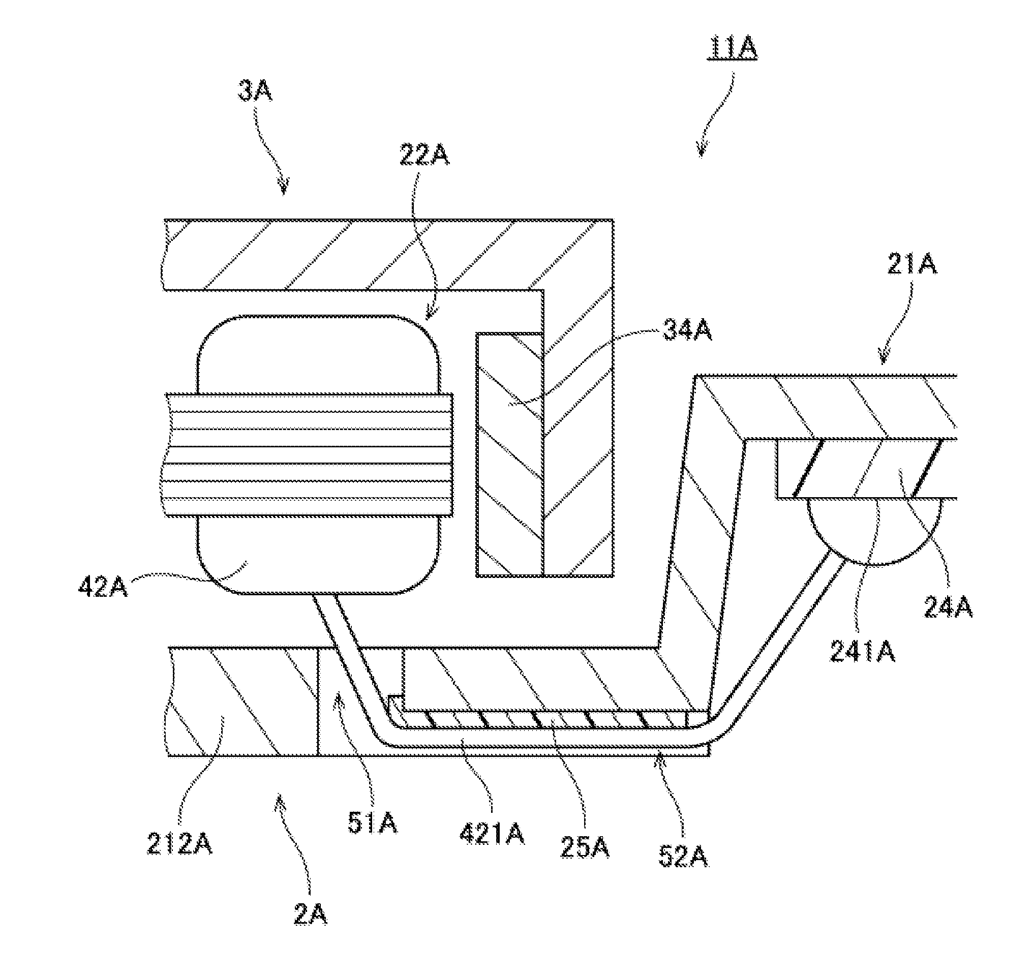
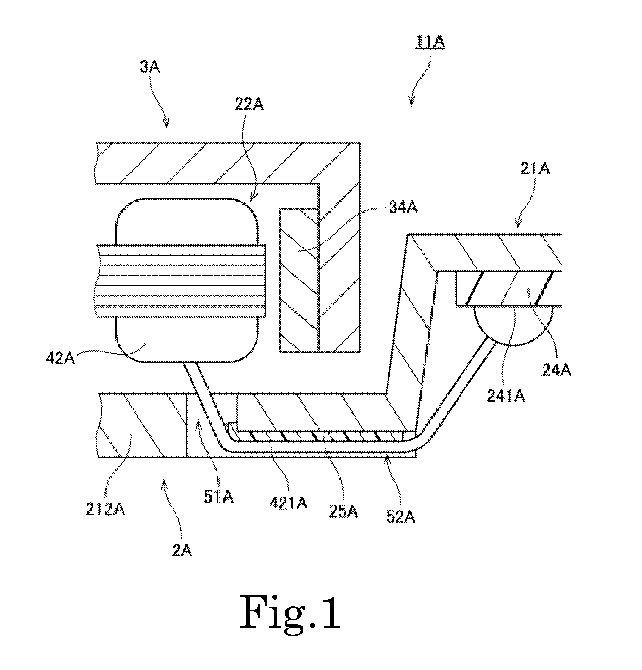
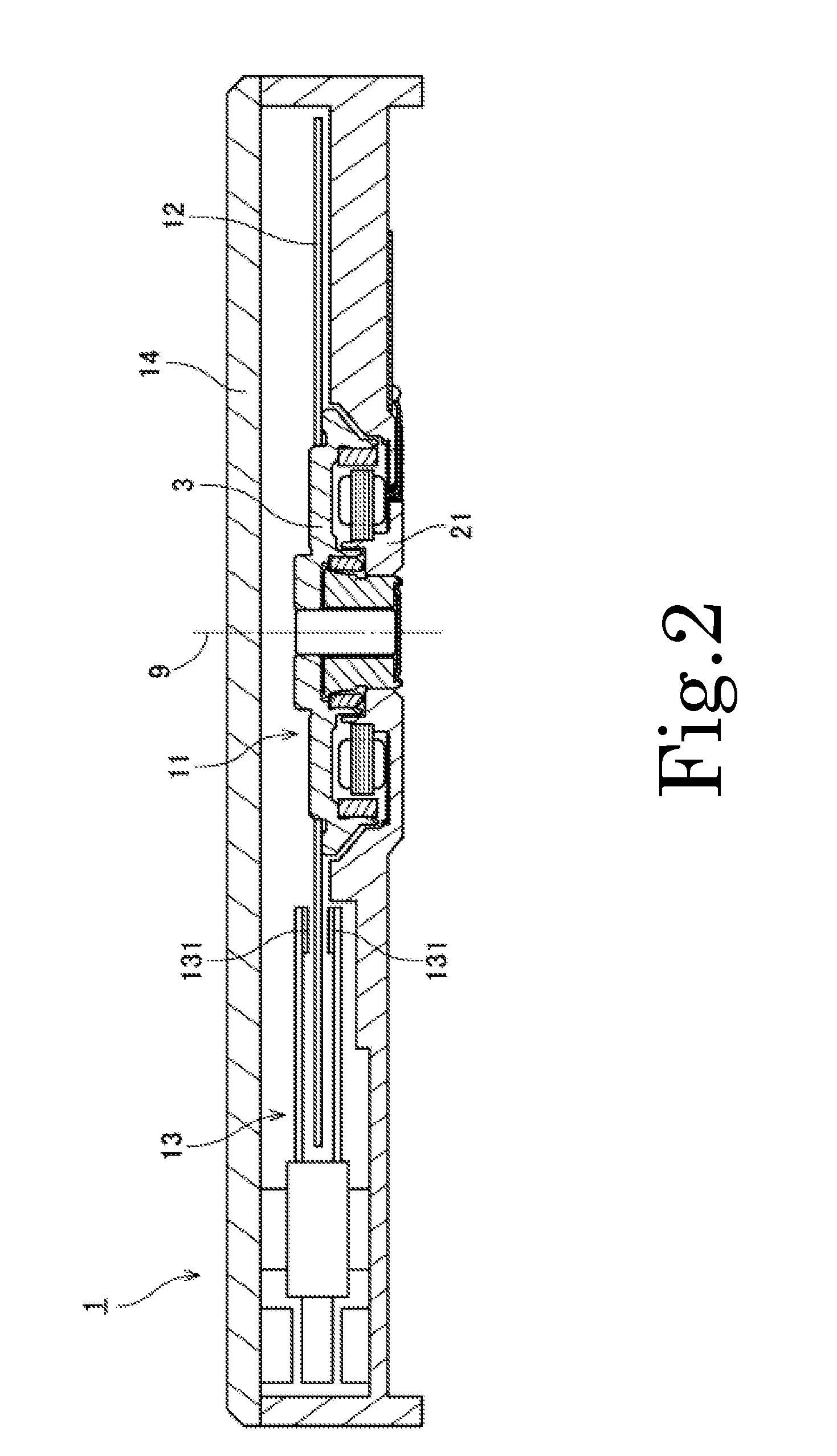
[0036]Hereinafter, illustrative preferred embodiments of the present invention will now be described with reference to the drawings. In the subject application, the direction parallel to the center axis of a spindle motor will be referred to as “axial”. The direction orthogonal to the center axis of the spindle motor will be referred to as “radial”. The direction extending along an arc about the center axis of the spindle motor will be referred to as “circumferential”. In the subject application, the shape and positional relationship of individual components will be described under the assumption that the axial direction is an up-down direction and further that the side of an armature with respect to a base member is an upper side. However, such definition of the up-down direction is not intended to limit the in-use direction of the spindle motor and the disk drive apparatus according to the present invention.

[0037]In the subject application, the term “parallel” includes the term “s...


PUM


Abstract

A base member includes a base through-hole which interconnects an upper opening and a lower opening. An insulating sheet portion is disposed at a lower surface side of the base member. The insulating sheet portion covers at least a portion of the lower opening. Lead wires extending from coils extend to the lower surface side of the base member through the base through-hole. The lead wires extend radially outward along a lower surface of the insulating sheet portion while making contact with the insulating sheet portion. The lead wires are soldered to land portions of a circuit substrate. The lower opening is covered with a sealing material. The circuit substrate includes a first region. The insulating sheet portion is defined by a smaller number of layers than the first region.

Description

BACKGROUND OF THE INVENTION[0001]1. Field of the Invention[0002]The present invention relates to a spindle motor and a disk drive apparatus.[0003]2. Description of the Related Art[0004]A hard disk device or an optical disk device is typically equipped with a spindle motor for rotating a disk. The spindle motor includes a stationary unit fixed to a housing of a device and a rotary unit rotating together with a disk supported thereon. In the spindle motor, torque acting about a center axis is generated by magnetic fluxes generated between the stationary unit and the rotary unit, whereby the rotary unit is rotated with respect to the stationary unit.[0005]A conventional spindle motor is disclosed in, e.g., Japanese Patent Application Publication No. 2011-114892. The spindle motor disclosed in the above-cited reference includes a base member, coils and a circuit substrate. Lead wires extending from the coils extend via through-holes of the base member and are connected to the circuit su...

Claims


Application Information

Patent Timeline
IPC IPC(8): H02K3/38H02K3/28G11B19/20
CPCH02K3/38H02K3/28G11B19/2009H02K3/50H02K5/225H02K2203/06H02K2211/03
Inventor SATO, KAZUHIROSHIRAISHI, MASAHIROISHINO, TAKAYUKIYUDATE, AKIHIROMATSUMOTO, TAKUROAKIYAMA, TOSHIHIRO
Owner NIDEC CORP
Why Eureka
Try Eureka