Current mode controlled power converter

a power converter and current mode technology, applied in the field of current mode control power converters, can solve the problems of increasing the number of components, increasing not only the manufacturing cost, but also the converter dimension, and the updating delay, so as to reduce the manufacturing cost and converter dimensions, prevent subharmonic oscillation reliably, and extend the input and output voltage range available for digital current mode control.

Active Publication Date: 2014-03-06
DENSO CORP
View PDF13 Cites 8 Cited by
  • Summary
  • Abstract
  • Description
  • Claims
  • Application Information

AI Technical Summary

Benefits of technology

[0013]In this configuration, for each control period based on the reference signal, the slope compensation signal calculated previous to or prior to the control period is negated during the slope calculation period, and the reset signal is generated on the basis of the error signal. This can prevent subharmonic oscillation reliably from occurring irrespective of the duty ratio and allows an input and output voltage range available for the digital current mode control to be extended. Further, this enables the digital current mode control even during an on time, and can reduce manufacturing costs and converter dimensions.
[0014]In one embodiment, the reset signal generation unit may configured to negate the slope compensation signal on the basis of the reference signal or the reset signal. This can prevent subharmonic oscillation more reliably from occurring irrespective of the duty ratio.
[0015]In one embodiment, the reset signal generation unit may be configured such that the timing of updating the current instruction to the second current instruction or the timing of updating the comparative signal to the second comparative signal is within a time period from the calculation completion of the slope compensation signal to the timing at which the duty ratio becomes 0.5 (50%). This can prevent subharmonic oscillation more reliably from occurring irrespective of the duty ratio.

Problems solved by technology

Implementation of such an analog slope compensation value calculation circuit will inevitably lead to an increase of number of components, which may increase not only manufacturing costs, but also converter dimensions.
Digitally processing the slope compensation in the microcomputer will, however, lead to an updating delay such that the timing of updating a current instruction is delayed by a calculation time required to calculate the current instruction.
Therefore, only with digitally processing of the slope compensation in the microcomputer, there is another disadvantage that the on time has to be greater than the calculation time.
Although a microcomputer operable at high frequencies is able to reduce the on time, the on time will still have to be greater than the calculation time, which leads to still another disadvantage that the microcomputer becomes more expensive.
Load variations and the like may cause a current reference signal (Iref) to change at time t65 as shown in FIG. 12, where a slope compensation signal calculated previous to a control cycle of time t65 to time t69 may remain, for example, at time t66, which gives rise to a further disadvantage that the voltage control is disabled until completion of the calculation and the DC-DC converter may malfunction at an improper duty ratio.

Method used


Image

  • Current mode controlled power converter
  • Current mode controlled power converter
  • Current mode controlled power converter

Examples


first embodiment

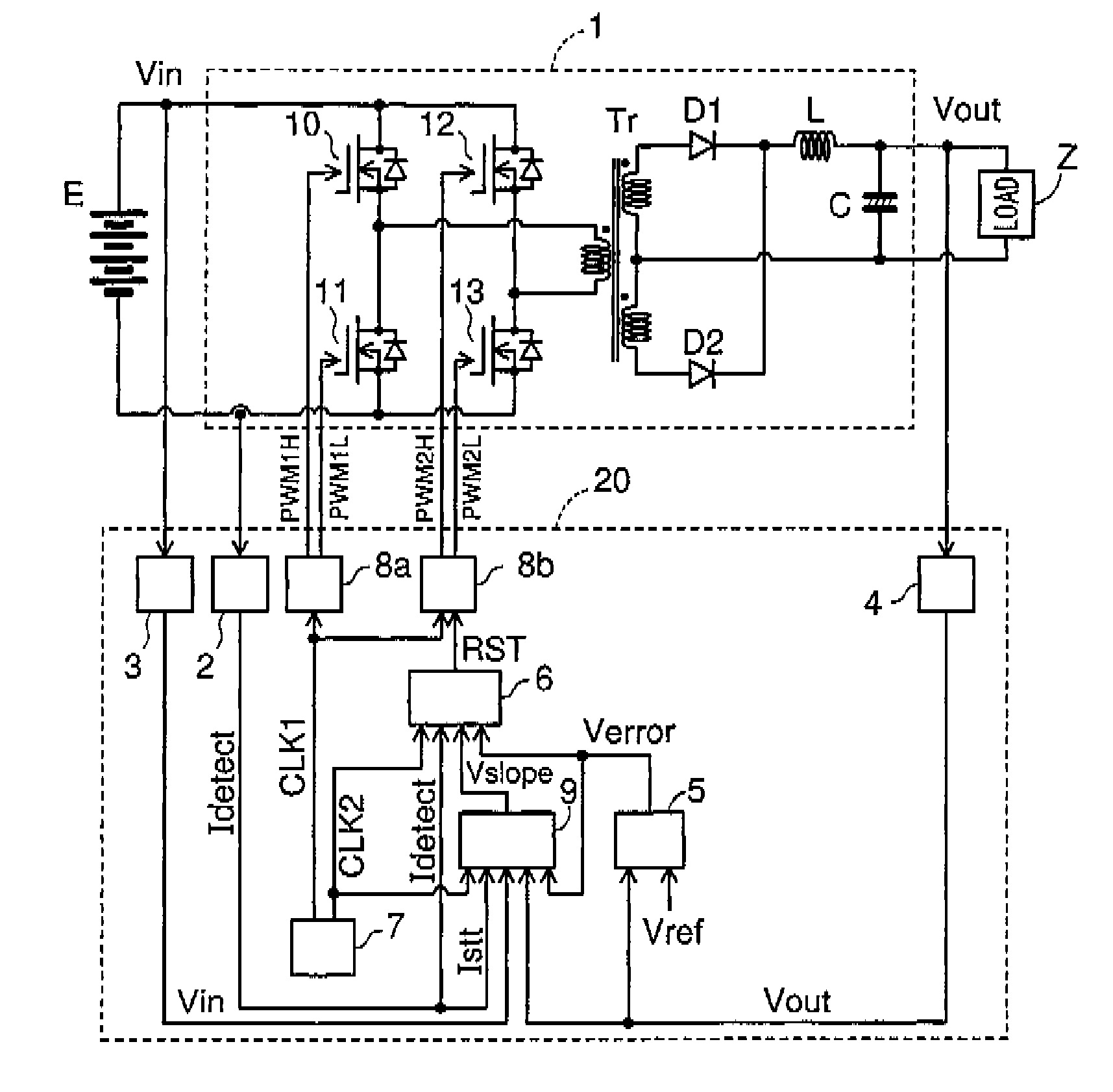
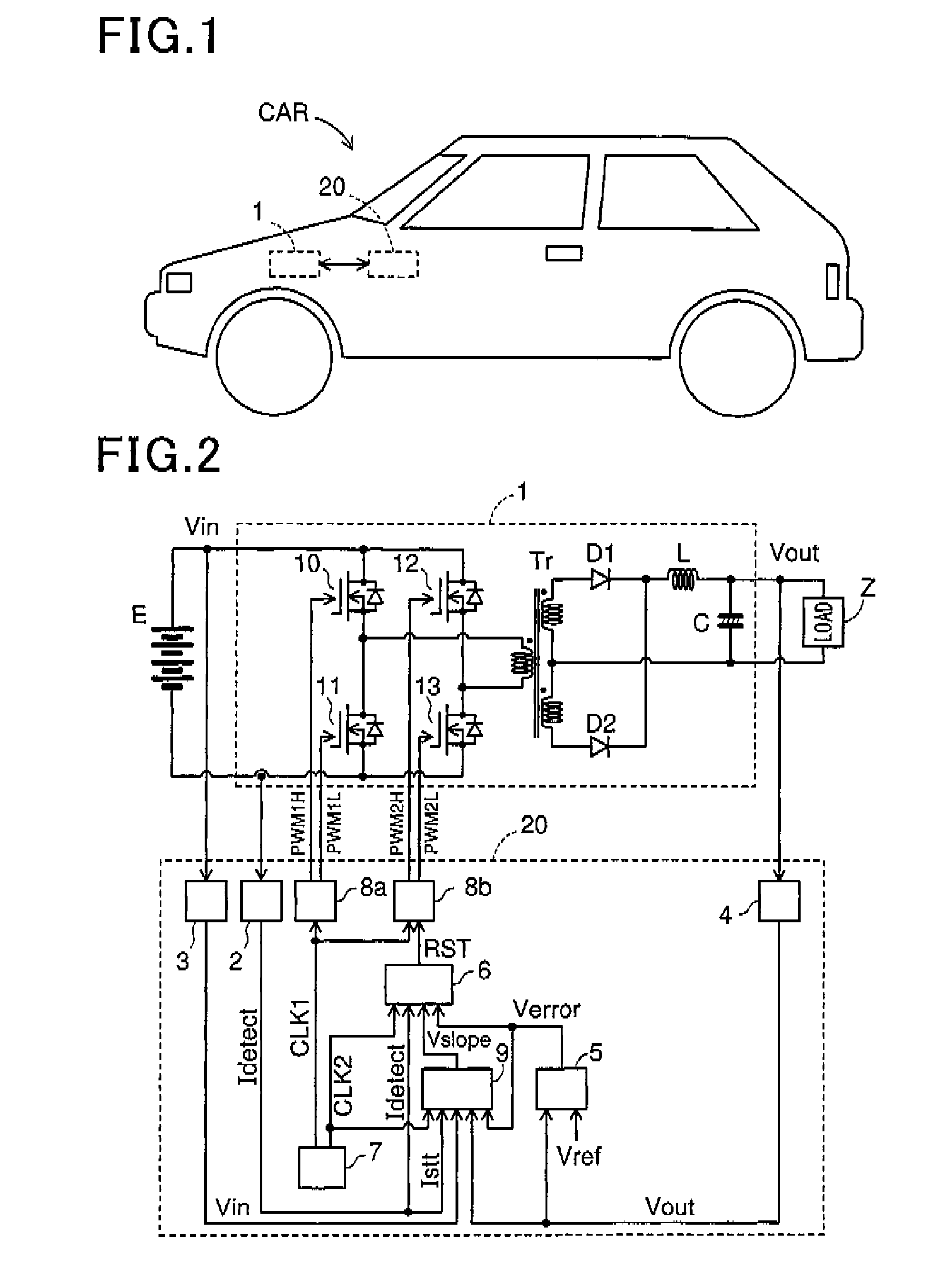
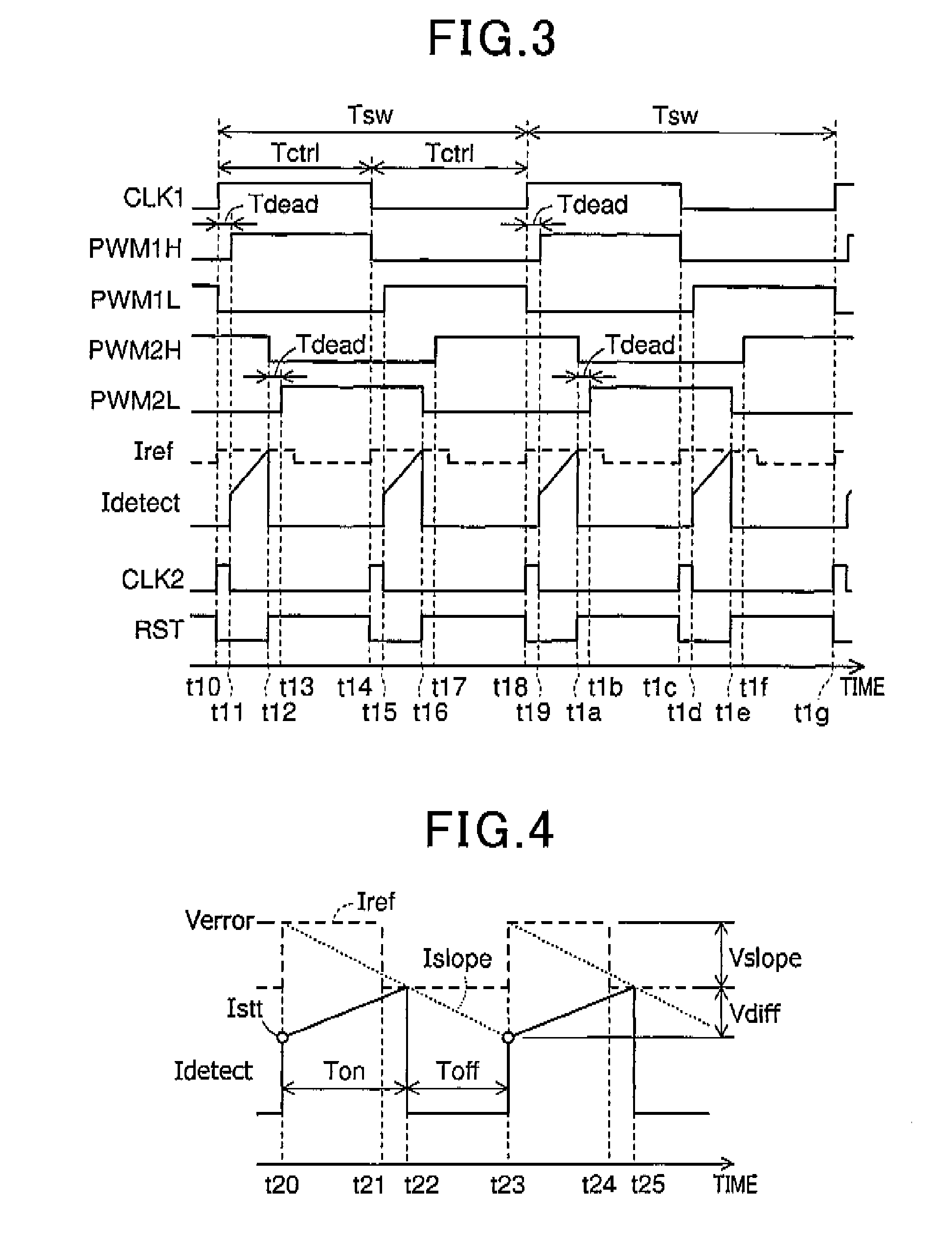
[0030]There will now be explained a first embodiment with reference to FIG. 1 to FIG. 5, and FIG. 11, where, for each control cycle, a slope compensation signal calculated on the basis of an error signal prior to the control cycle is negated. A car shown in FIG. 1 is provided with a power converter including a switching section 1 and a control section 20. The switching section 1 and the control section 20 may be separate from each other, where the switching section 1 may also be referred to as a switching unit, or may be integrated together. FIG. 2 shows an exemplary configuration of the switching section 1 and the control section 20.

[0031]As shown in FIG. 2, the switching section 1, which serves as a so called DC-DC converter, converts an input voltage value Vin into a desired voltage value through the switching operation and outputs the voltage of the desired voltage value. The switching section 1 includes switching modules 10, 11, 12, 13, a transformer Tr, diodes D1, D2, a reacto...

second embodiment

[0062]There will now be explained the second embodiment of the present invention with reference to FIG. 6 to FIG. 8, and FIG. 11, where the slope compensation signal is negated on the basis of the reference signal or the reset signal. Only differences of the second embodiment from the first embodiment will be explained. Elements having the same functions as in the first embodiment are assigned the same numbers and will not be described again for brevity.

[0063]The power converter, including the switching section 1 and the control section 20, of the present embodiment shown in FIG. 6 differs from the power converter, including the switching section 1 and the control section 20, of the first embodiment shown in FIG. 1 in that the slope compensation unit 9 further receives the reset signal RST outputted from the reset signal generation unit 6. The slope compensation unit 9 is configured such that the slope compensation signal Vslope is negated on the basis of the reference signal CLK2 o...

third embodiment

[0075]There will now be explained a third embodiment of the present invention with reference to FIG. 9 to FIG. 11, where, as in the second embodiment, the slope compensation signal is negated on the basis of the reference signal or the reset signal. Only differences of the third embodiment from the first and second embodiments will be explained. Elements having the same functions as in the first and second embodiments are assigned the same numbers and will not be described again for brevity.

[0076]FIG. 9 shows a block diagram of the reset signal generation unit 6, as alternative to the reset signal generation unit 6 shown in FIG. 7. In the third embodiment, the slope compensation is performed by adding the slope compensation signal Vslope to the current detection signal Idetect while in the second embodiment the slope compensation is performed by subtracting the slope compensation signal Vslope from the error signal Verror.

[0077]The reset signal generation unit 6 shown in FIG. 9 incl...


PUM


Abstract

A current mode controlled power converter controllable in a digitally processing current mode even during an on time. In the power converter, each control period based on a reference signal includes a slope calculation period in which a slope compensation signal for the control period is calculated by a slope compensation unit. During each slope calculation period, the slope compensation unit negates the slope compensation signal calculated previous to the control period including the slope calculation period, and a reset signal generation unit compares a current detection signal detected by a current detection unit with a current instruction set to an error signal generated by an error signal generation unit to generate a reset signal.

Description

CROSS-REFERENCE TO RELATED APPLICATION[0001]This application is based on and claims the benefit of priority from earlier Japanese Patent Application No. 2012-192149 filed Aug. 31, 2012, the description of which is incorporated herein by reference.BACKGROUND[0002]1. Technical Field[0003]The present invention relates to a current mode controlled power converter.[0004]2. Related Art[0005]A current mode controlled power converter essentially includes slope compensation means for preventing subharmonic oscillation and needs an external slope circuit to implement the slope compensation means.[0006]An example of technique used in a known DC-DC converter as disclosed in Japanese Patent Application Laid-Open Publication No. 2011-101479 is intended to implement slope compensation upon dynamic changes in output voltage while allowing for stable operation with low power consumption and high efficiency. This DC-DC converter includes an output voltage setting register for storing a voltage settin...

Claims


Application Information

Patent Timeline
Patent Type & Authority Applications(United States)
IPC IPC(8): H03K5/12
CPCH03K5/12
Inventor KINJOU, HIROFUMIHAYASHI, YUJISHIGEOKA, KEIJINAKAMURA, KIMIKAZU
Owner DENSO CORP
Why Eureka
Try Eureka