AI technical title is built by PatSnap AI team. It summarizes the technical point description of the patent document.
a power amplifier and switch technology, applied in the direction of amplifiers with semiconductor devices/discharge tubes, dc amplifiers with modulator-demodulator, etc., can solve the problems of large heat, inefficient power usage, and inefficient class a amplifiers in terms of power usage, so as to maintain the overall signal gain and avoid oscillation
Inactive Publication Date: 2008-07-15
RODRIGUEZ MANUEL DE JESUS
View PDF24 Cites 37 Cited by
Summary
Abstract
Description
Claims
Application Information
AI Technical Summary
This helps you quickly interpret patents by identifying the three key elements:
Problems solved by technology
Method used
Benefits of technology
Benefits of technology
[0068]a phase lag compensation coupled between the power output stage and the modulator to modify phases of the main output signal in relation to that of the main input signal for avoiding oscillations.
Problems solved by technology
In general, class A amplifiers produce a linearly amplified replica of an input signal, but are inefficient in terms of power usage (generating a great amount of heat) because the amplifying elements are always biased and conducting, even if there is no input.
In general, class A amplifiers are inefficient in terms of power usage because the amplifying element(s) are always biased and conducting, even if there is no input signal to be amplified.
However, this is also the cause for the inefficiency of this type of amplifier.
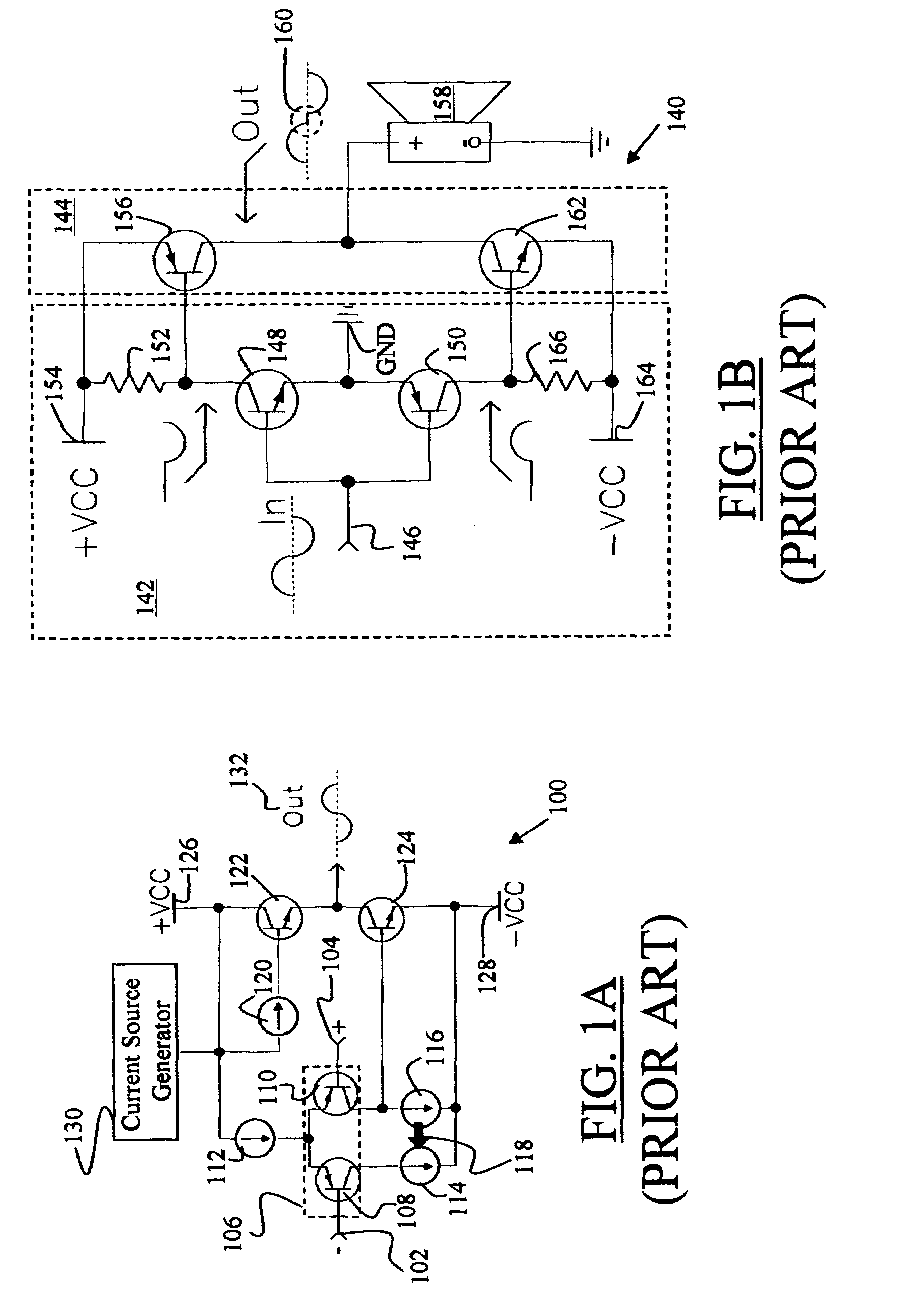
However, this introduces crossover distortion caused by a small glitch 160 (FIG. 1B) at the “link” between the two halves of the signal generated by the sink and the source.
Regrettably, most solutions to reduce the crossover distortion (the small glitch 160 at the link between the two halves of the signal) reduce the efficiency of the class B amplifiers.
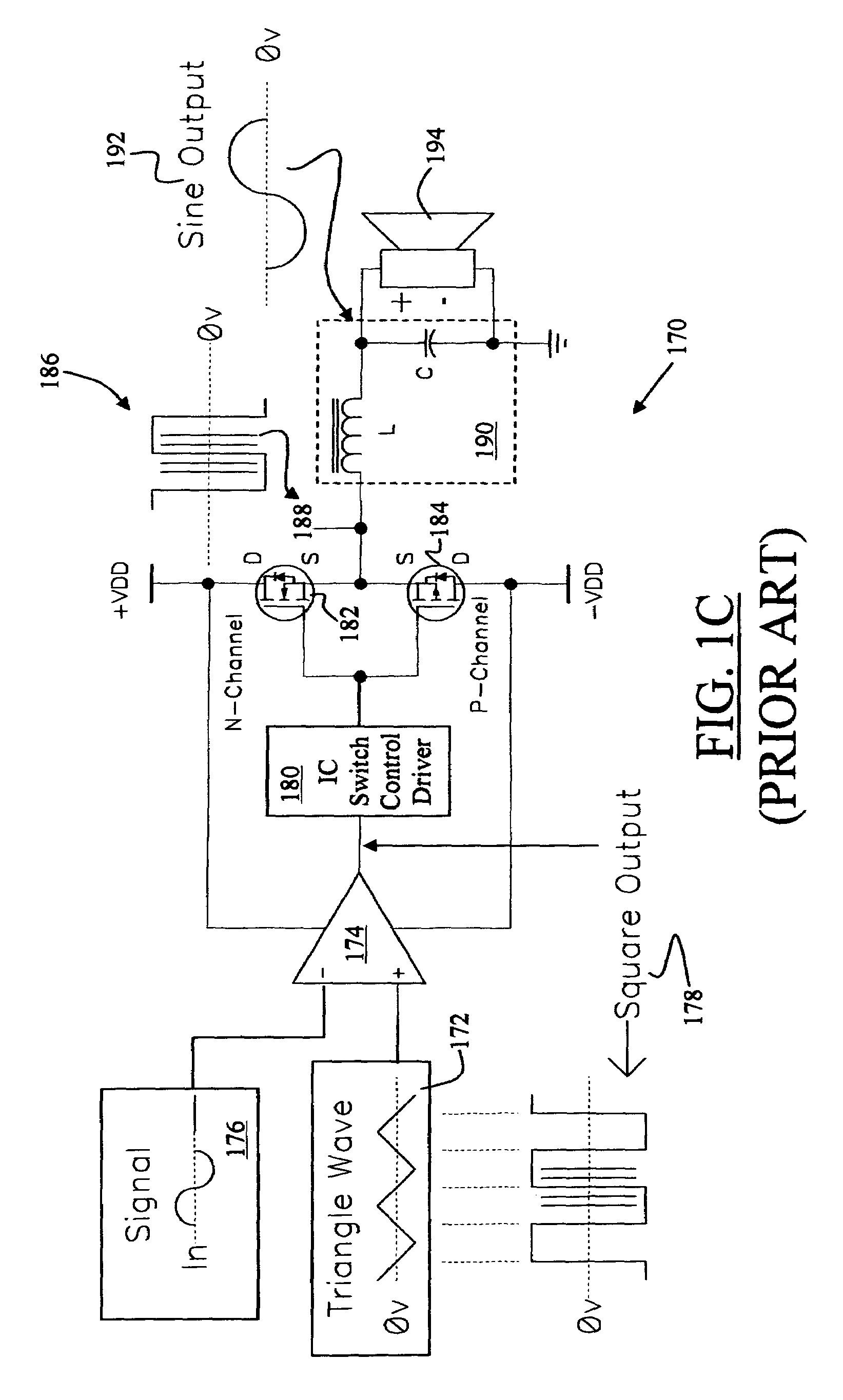
This design approach produces an amplifier with better than 90% efficiency, but is much more complex than its linear counterpart (class A or class B amplifiers).
Despite their efficiency, most class D amplifiers are comprised of complex proprietary Integrated Circuits (ICs) for control of the switches, cannot accurately reproduce the input waveform except for low fidelity applications, and are subject to power supply perturbations.
In summary, class A amplifiers produce a linearly amplified replica of an input signal, but are inefficient in terms of power usage.
The push-pull class B amplifiers provide excellent efficiency (compared to class A amplifiers), but introduce crossover distortion.
Class D amplifiers are efficient, and produce a fairly accurate linearly amplified replica of an input signal, but are comprised of complex proprietary Integrated Circuits (ICs) for control of the power output switches, and require power regulation for proper operation.
Method used
Image
Click on the blue label to locate the original text in one second.
Reading with bidirectional positioning of images and text.
Examples
Embodiment Construction
[0117]The detailed description set forth below in connection with the appended drawings is intended as a description of presently preferred embodiments of the invention and is not intended to represent the only forms in which the present invention may be constructed and or utilized.
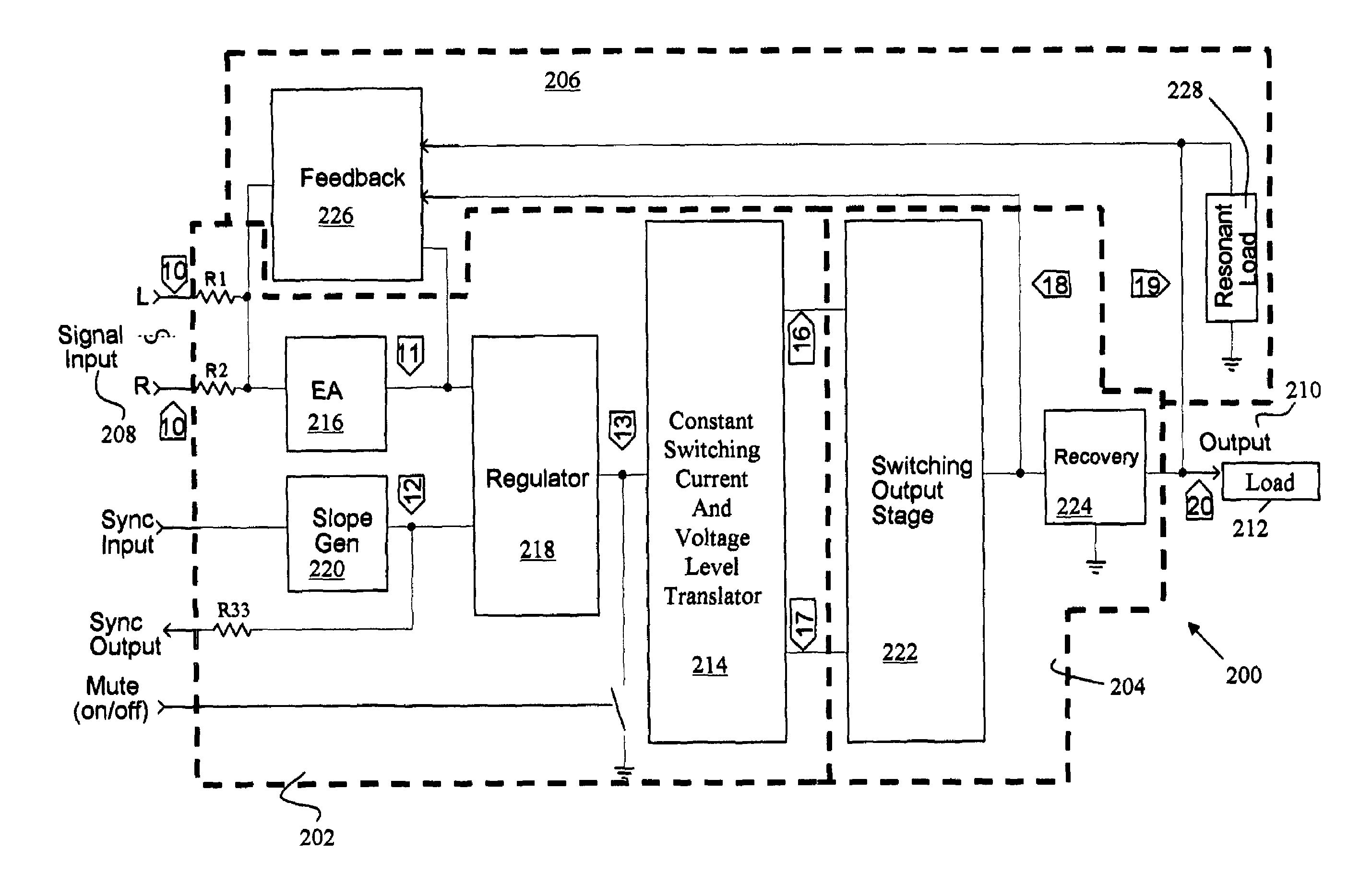
[0118]FIG. 2A is an exemplary simplified schematic block diagram illustration of a switching power amplifier 200 in accordance with the present invention, and FIGS. 3(A) to 3(N) are exemplary waveform diagrams illustrating the various waveforms at particular points in the circuits of FIGS. 2A to 2C, and FIGS. 4 to 11. As illustrated, the present invention discloses a switching power amplifier 200 that produces a linearly amplified replica of an input signal, provides the advantages and the functionality of a class D amplifier, but without the problems in relation to complex circuit topography and proprietary aspect related to the class D amplifiers, and does not require a regulated power supply.
[0119]As i...
PUM
Abstract
The present invention discloses a switching amplifier, comprising a modulator for converting a main input signal to a high frequency modulated switching signal and for providing voltage amplification of the main input signal. The present invention further includes a power output stage coupled with an output of the modulator for receiving the voltage amplified main input signal and for providing a current amplification of the main input signal for providing a main output signal for deriving a load. Further included is a feedback module for correction of the main output signal in relation to the main input signal.
Description
BACKGROUND OF THE INVENTION[0001](1) Field of the Invention[0002]This invention relates to power amplifiers and, more particularly, to switching power amplifiers that can efficiently and linearly amplify a signal.[0003](2) Description of Related Art[0004]Amplifiers are electronic devices that are used for increasing the power of a signal, and are generally categorized into various classes. Reference is made to the exemplary U.S. Patents that disclose various types of amplifiers: U.S. Pat. Nos. 6,563,377; 6,498,531; 6,429737; 6,356,151; 6,297,692; 6,282,747; 6,246,283; 6,229,388; 6,097,249; 6,091,292; 6,078,214; 6,072,361; 6,016,075; 5,982,231; 5,973,368; 5,963,086; 5,838,193; 5,805,020; 5,617,058; 5,160,8969; 5,014,016; 4,531,096; and 3,629,616.[0005]In general, class A amplifiers produce a linearly amplified replica of an input signal, but are inefficient in terms of power usage (generating a great amount of heat) because the amplifying elements are always biased and conducting, ev...
Claims
Application Information
Patent Timeline
Application Date:The date an application was filed.
Publication Date:The date a patent or application was officially published.
First Publication Date:The earliest publication date of a patent with the same application number.
Issue Date:Publication date of the patent grant document.
PCT Entry Date:The Entry date of PCT National Phase.
Estimated Expiry Date:The statutory expiry date of a patent right according to the Patent Law, and it is the longest term of protection that the patent right can achieve without the termination of the patent right due to other reasons(Term extension factor has been taken into account ).
Invalid Date:Actual expiry date is based on effective date or publication date of legal transaction data of invalid patent.

