Current-mode controlled switching regulator and control method therefor

a switching regulator and current mode technology, applied in the direction of dc-dc conversion, power conversion systems, instruments, etc., can solve the problems of subharmonic oscillation, slow response to fluctuation in output voltage, and complicated phase compensation of error amplifiers that amplify the voltage difference between output voltage and reference voltag

Inactive Publication Date: 2008-06-26
RICOH ELECTRONIC DEVICES CO LTD
View PDF2 Cites 38 Cited by
  • Summary
  • Abstract
  • Description
  • Claims
  • Application Information

AI Technical Summary

Benefits of technology

[0018]This patent specification describes a novel current-mode controlled step-down switching regulator that includes an input terminal, an output terminal, a switching device to switch in accordance with a control signal, an inductor to store charge from an input voltage at the input terminal based on the switching device, a rectifying device to discharge the charge stored in the inductor, an error amplifier to amplify a voltage difference between a divided voltage generated by dividing an output voltage at the output terminal and a predetermined reference voltage, a slope voltage generator to generate and output a slope voltage having a slope angle corresponding to the input voltage, and a switching controller to compare a voltage output from the error amplifier with the slope voltage, generate a pulse signal with a duty cycle corresponding to a comparison result, and control the switching of the switching device according to the pulse signal.
[0019]This patent specification further describes a novel current-mode controlled step-up switching regulator that includes an input terminal, an output terminal, a switching device to switch in accordance with a control signal, an inductor to store charge from an input voltage at the input terminal based on the switching device, a rectifying devi

Problems solved by technology

However, since such a voltage-mode controlled switching regulator detects a feedback signal from the output voltage, response to fluctuation in the output voltage is slow.
Further, phase compensation for an error amplifier that amplifies the voltage difference between the output voltage and the reference voltage becomes complicated.
However, it is known that subharmonic

Method used


Image

  • Current-mode controlled switching regulator and control method therefor
  • Current-mode controlled switching regulator and control method therefor
  • Current-mode controlled switching regulator and control method therefor

Examples


first embodiment

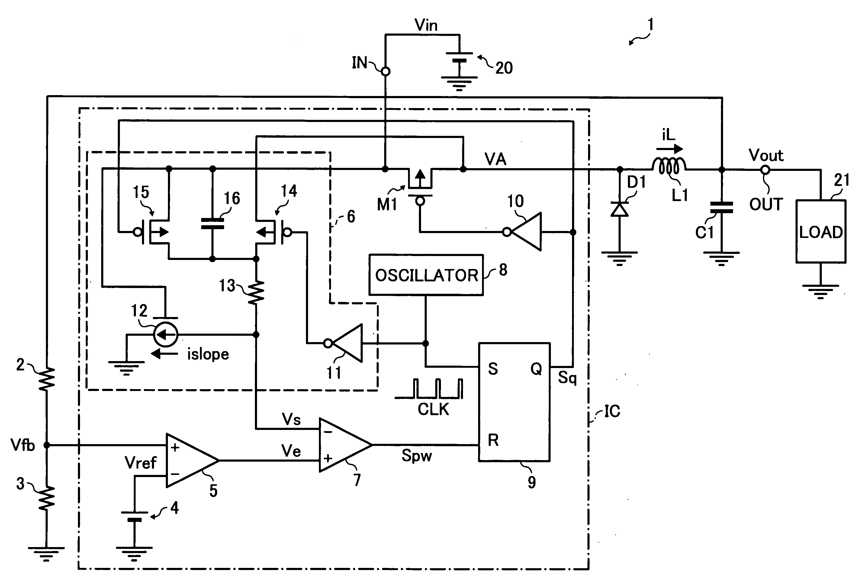
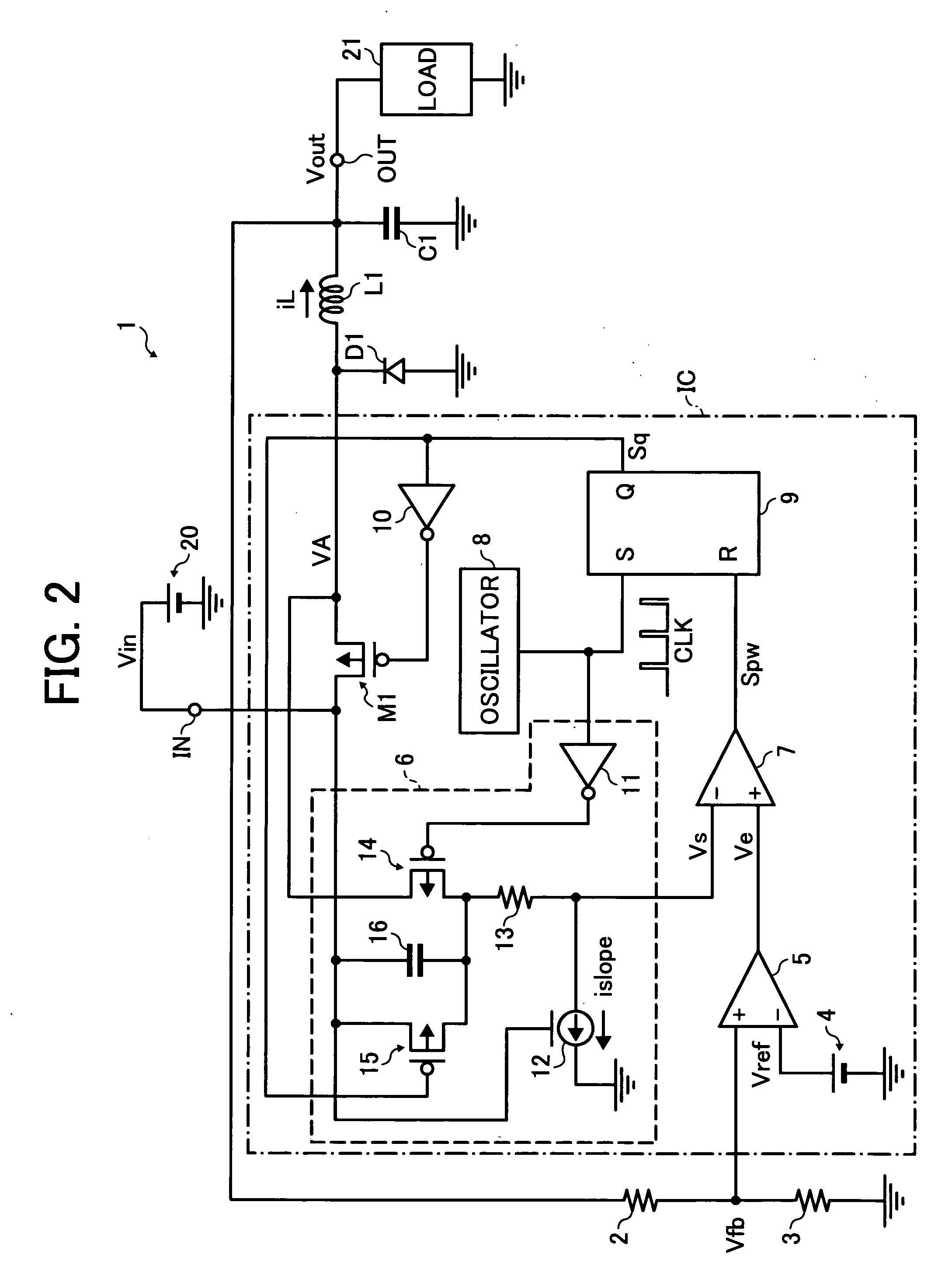
[0032]FIG. 2 is a diagram illustrating example circuitry of a current-mode controlled switching regulator according to a

[0033]A current-mode controlled switching regulator (hereinafter referred to as a switching regulator) 1 of FIG. 2 forms a step-down switching regulator that converts an input voltage Vin applied from a DC (direct current) power supply 20 to an input terminal IN into a lower voltage than the input voltage Vin and outputs an output voltage Vout from an output terminal OUT to a load 21.

[0034]The switching regulator 1 includes a PMOS switching transistor M1 that controls output of a current flowing from the input terminal IN, a rectifying diode D1, an inductor L1, a smoothing capacitor C1, and output voltage detecting resistors 2 and 3 that divide the output voltage Vout output from the output terminal OUT, and generate and output a divided voltage Vfb.

[0035]The switching regulator 1 also includes a reference voltage generator 4 that generates and outputs a reference ...

second embodiment

[0066]FIG. 5 is a diagram illustrating example circuitry of a current-mode controlled switching regulator according to the In FIG. 5, the same or similar components to those illustrated in FIG. 2 are referred to by the same reference numerals.

[0067]A switching regulator 1a of FIG. 5 forms a step-up switching regulator that converts an input voltage Vin applied from a DC power supply 20 to an input terminal IN into a higher voltage than the input voltage Vin and outputs an output voltage Vout from an output terminal OUT to a load 21.

[0068]The switching regulator 1a includes a NMOS switching transistor M11, a rectifying diode D11, an inductor L1, a smoothing capacitor C1, and output voltage detecting resistors 2 and 3 that divide the output voltage Vout output from the output terminal OUT and generate and output a divided voltage Vfb.

[0069]The switching regulator 1a also includes a reference voltage generator 4 that generates and outputs a reference voltage Vref, an error amplifier 5...


PUM


Abstract

A current-mode controlled switching regulator and control method therefor. The switching regulator includes input and output terminals, a switching device to switch in accordance with a control signal, an inductor to store charge from an input voltage at the input terminal based on the switching device, a rectifying device to discharge the charge stored in the inductor, an error amplifier to amplify a voltage difference between a divided voltage generated by dividing an output voltage at the output terminal and a predetermined reference voltage, a slope voltage generator to generate and output a slope voltage having a slope angle corresponding to the input voltage, and a switching controller to compare a voltage output from the error amplifier with the slope voltage, generate a pulse signal with a duty cycle corresponding to a comparison result, and control the switching of the switching device according to the pulse signal.

Description

CROSS-REFERENCE TO RELATED APPLICATION[0001]This patent specification is based on and claims priority from Japanese Patent Application No. 2006-349020 filed on Dec. 26, 2006 in the Japan Patent Office, the entire contents of which are hereby incorporated by reference herein.BACKGROUND[0002]1. Field of the Invention[0003]The present invention relates to a current-mode controlled switching regulator and a control method therefor.[0004]2. Description of the Related Art[0005]Until recently, a switching regulator has generally employed a voltage-mode control system, in which a switching device is controlled by PWM (pulse width modulation) control based on the voltage difference between an output voltage and a reference voltage to stabilize the output voltage. However, since such a voltage-mode controlled switching regulator detects a feedback signal from the output voltage, response to fluctuation in the output voltage is slow. Further, phase compensation for an error amplifier that ampl...

Claims


Application Information

Patent Timeline
IPC IPC(8): G05F1/10G05F1/00
CPCH02M3/156H02M2001/0025H02M2001/0022H02M1/0022H02M1/0025G05F1/10
Inventor SOHMA, SHOHTAROH
Owner RICOH ELECTRONIC DEVICES CO LTD
Why Eureka
Try Eureka