
Dual-band dual-orthogonal-polarization antenna element

Active Publication Date: 2013-01-08
THE UNITED STATES OF AMERICA AS REPRESENTED BY THE SECRETARY OF THE NAVY +1
View PDF8 Cites 55 Cited by
  • Summary
  • Abstract
  • Description
  • Claims
  • Application Information

AI Technical Summary

Benefits of technology

This patent describes a unique dual-band antenna element that can work with two different senses of circular polarization. It is designed with a printed circuit and has a low profile and low cost. The element can be easily integrated into various wireless communication devices. The size reduction technique allows for this element to be placed on an array lattice without overlapping with other elements, which makes it suitable for synthetic aperture radar and multifunction radar applications. Overall, this invention provides a simple and cost-effective solution for integrating a dual-band antenna element into various wireless devices.

Problems solved by technology

The majority of dual-band elements in the literature are not capable of providing simultaneous dual-CP operation at each polarization bands.

Method used


Image

  • Dual-band dual-orthogonal-polarization antenna element
  • Dual-band dual-orthogonal-polarization antenna element
  • Dual-band dual-orthogonal-polarization antenna element

Examples


Embodiment Construction

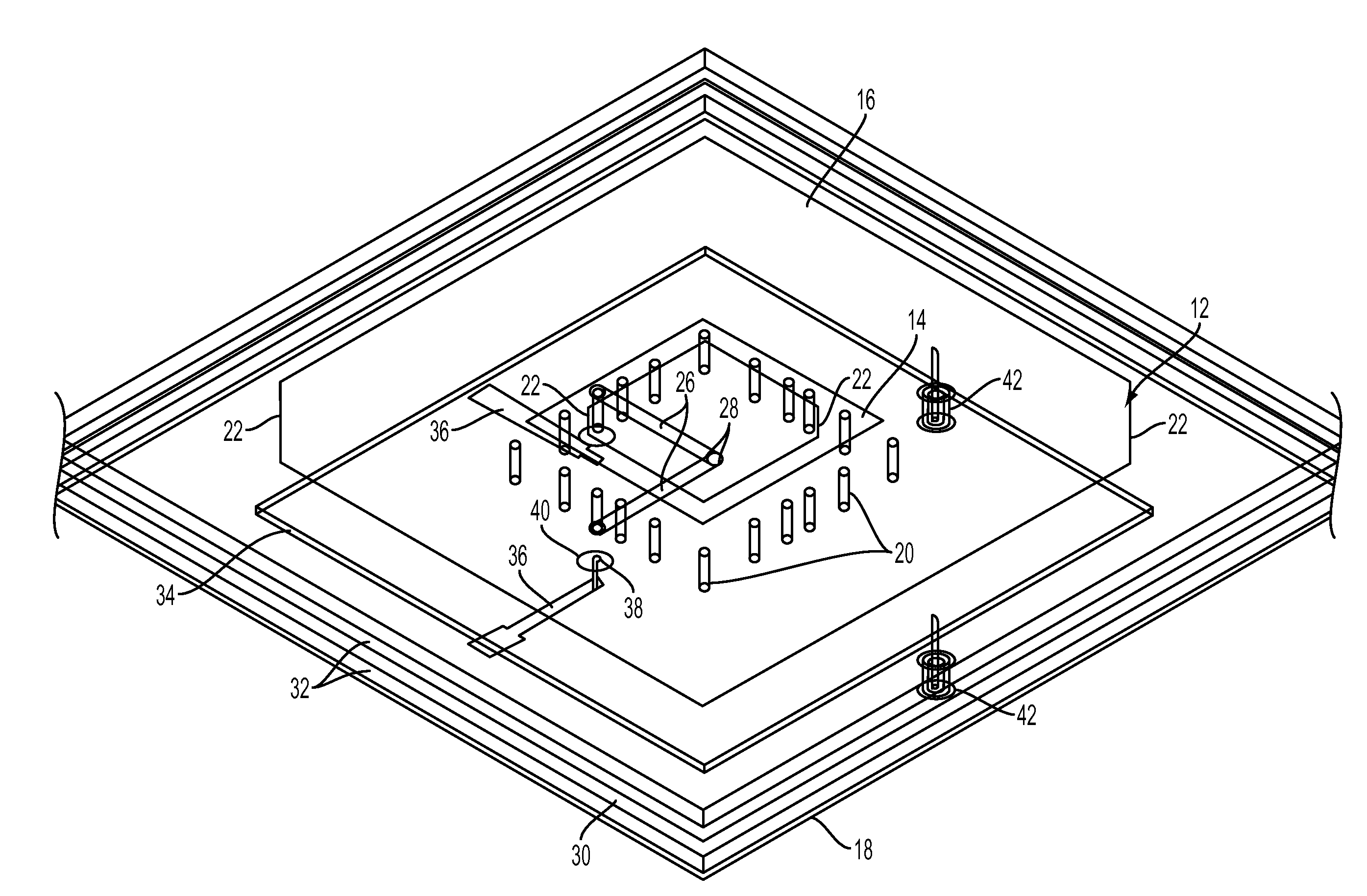
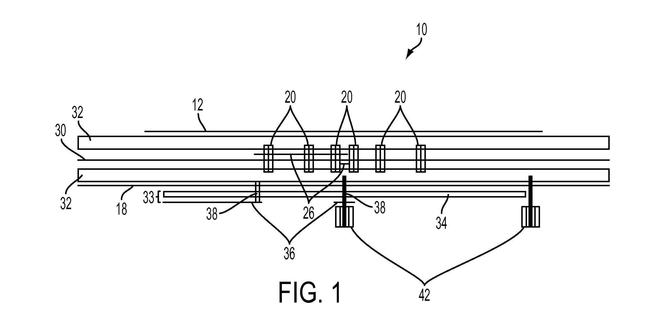
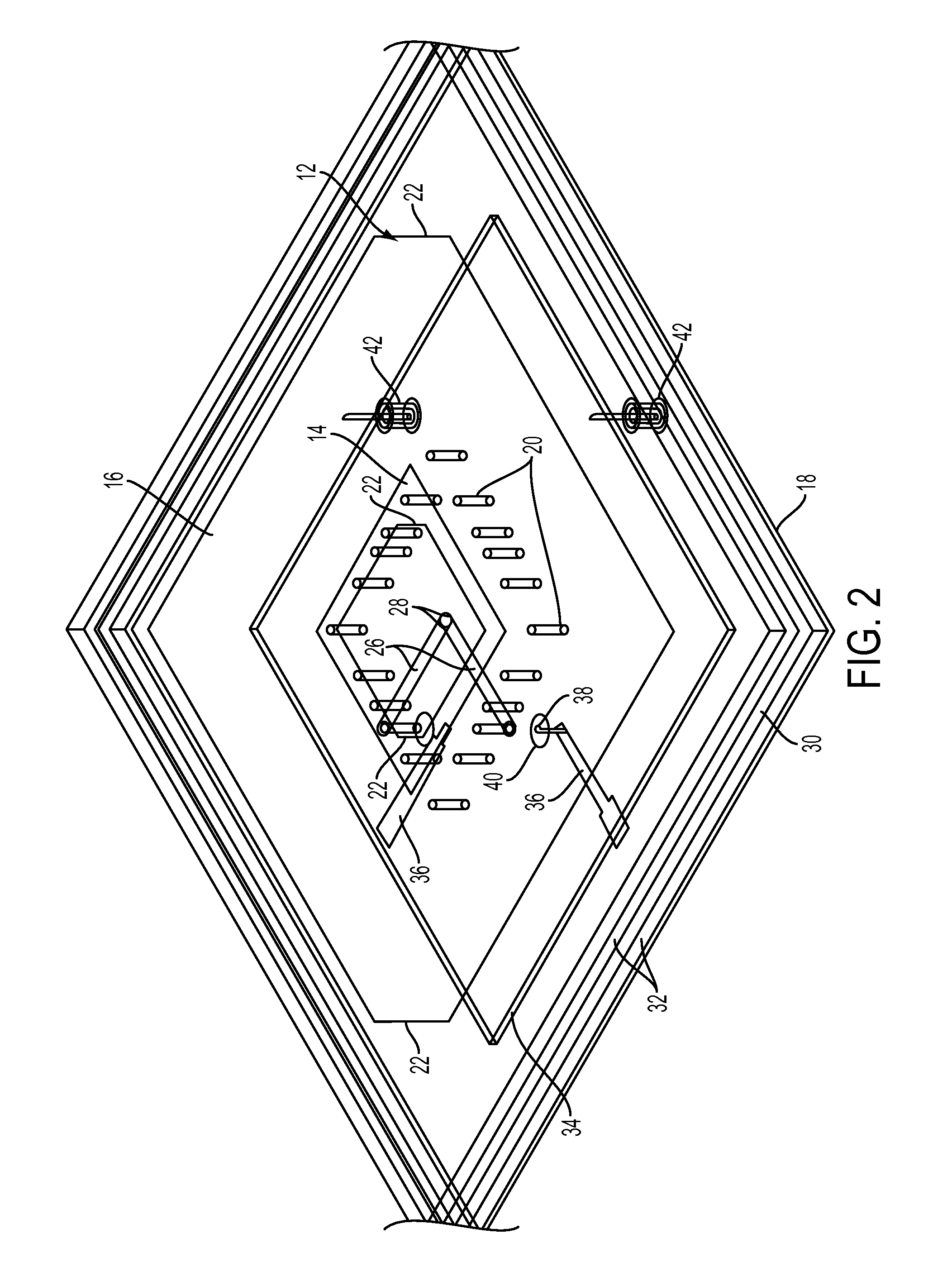
[0036]Referring now to FIGS. 1-5, a dual-band dual-orthogonally-polarized element 10 according to the invention includes a stratified arrangement of microwave substrate layers and planar conductor layers with vertical plated through holes providing interconnections between specified conductor layers. Conductor layer 12 includes a square ring slot 14 that operates as a slotted stripline circuit and is the high band radiator. Conductor layer 12 also includes a shorted square ring 16 that is present outside of the square ring slot 14 and serves as the low band radiator. The low band radiator is shorted to a conductor layer 18 that serves as the ground plane for the element with plated through holes 20 located at the inner perimeter of the shorted square ring 16. Isosceles triangular perturbations 22 are present at opposing corners of both the shorted square ring 16 and square ring slot 14. The use of these perturbations creates two, near-degenerate modes that excite CP with a single fe...


PUM


Abstract

A dual-band, dual-orthogonally-polarized antenna element includes a dielectric substrate having a conductor layer that includes a square ring slot and a shorted square ring, with each having a pair of orthogonal feed points. The shorted square ring is fed with coaxial probe feeds, while the square ring slot feeds striplines terminated in open-circuited stubs for coupling energy to each pair of orthogonal feed points. The first and second stripline feeds are not coplanar in order that each stub terminates past a center point of the element. The square ring slot operates as a high frequency band radiator and the shorted square ring operates as a low frequency band radiator, and both bands radiate substantially simultaneous dual-orthogonally-polarized modes. The modes can be any combination of dual-Circular Polarization (CP) and dual-Linear Polarization (LP), depending on the geometry of the radiators.

Description

CROSS-REFERENCE TO RELATED APPLICATIONS[0001]This Application claims the benefit of U.S. Provisional Application 61 / 183,266 filed on Jun. 2, 2009.TECHNICAL FIELD[0002]The invention is directed to an antenna for transmitting and receiving radio frequency signals, and more particularly, to a dual band antenna capable of simultaneously operating with two orthogonal senses of polarization in each band.BACKGROUND OF THE INVENTION[0003]Antennas capable of operating at multiple frequency bands are advantageous to many applications ranging from space-based radar to personal wireless communications. Synthetic aperture radar (SAR) typically operates in L- and C-bands. For space-based SAR applications where minimizing the mass and weight of the radar system is essential to reducing the overall cost of the mission, antennas capable of operating in multiple frequency bands with multiple polarizations are beneficial. Dual-band antenna elements are also desirable in radar applications because of t...

Claims


Application Information

Patent Timeline
IPC IPC(8): H01Q13/10
CPCH01Q9/0435H01Q5/40H01Q21/24H01Q13/106
Inventor ZAGHLOUL, AMIR IDORSEY, W MARK
Owner THE UNITED STATES OF AMERICA AS REPRESENTED BY THE SECRETARY OF THE NAVY
Learn More