Apparatus for starting engine mounted on-vehicle

a technology for starting engines and vehicles, applied in the direction of engine starters, machines/engines, relays, etc., can solve the problems of reducing manufacturing steps, avoiding working steps which have been necessary for manufacturing electromagnetic coils with two coils,

Active Publication Date: 2010-10-21
DENSO CORP
View PDF13 Cites 53 Cited by
  • Summary
  • Abstract
  • Description
  • Claims
  • Application Information

AI Technical Summary

Benefits of technology

[0016]In this preferred example, since the operations of both the solenoid pushing the pinion gear and the switch for current supply to the motor can be controlled independently of each other, it is possible to restart the engine during its rotation due to its inertia after an engine stop is instructed by an idle stop apparatus. In this situation, the switch can be activated before the act

Problems solved by technology

In addition, the foregoing working steps which have been necessary for manufacturing electromagnetic coils with two coils (consisting of an attraction

Method used


Image

  • Apparatus for starting engine mounted on-vehicle
  • Apparatus for starting engine mounted on-vehicle
  • Apparatus for starting engine mounted on-vehicle

Examples


first embodiment

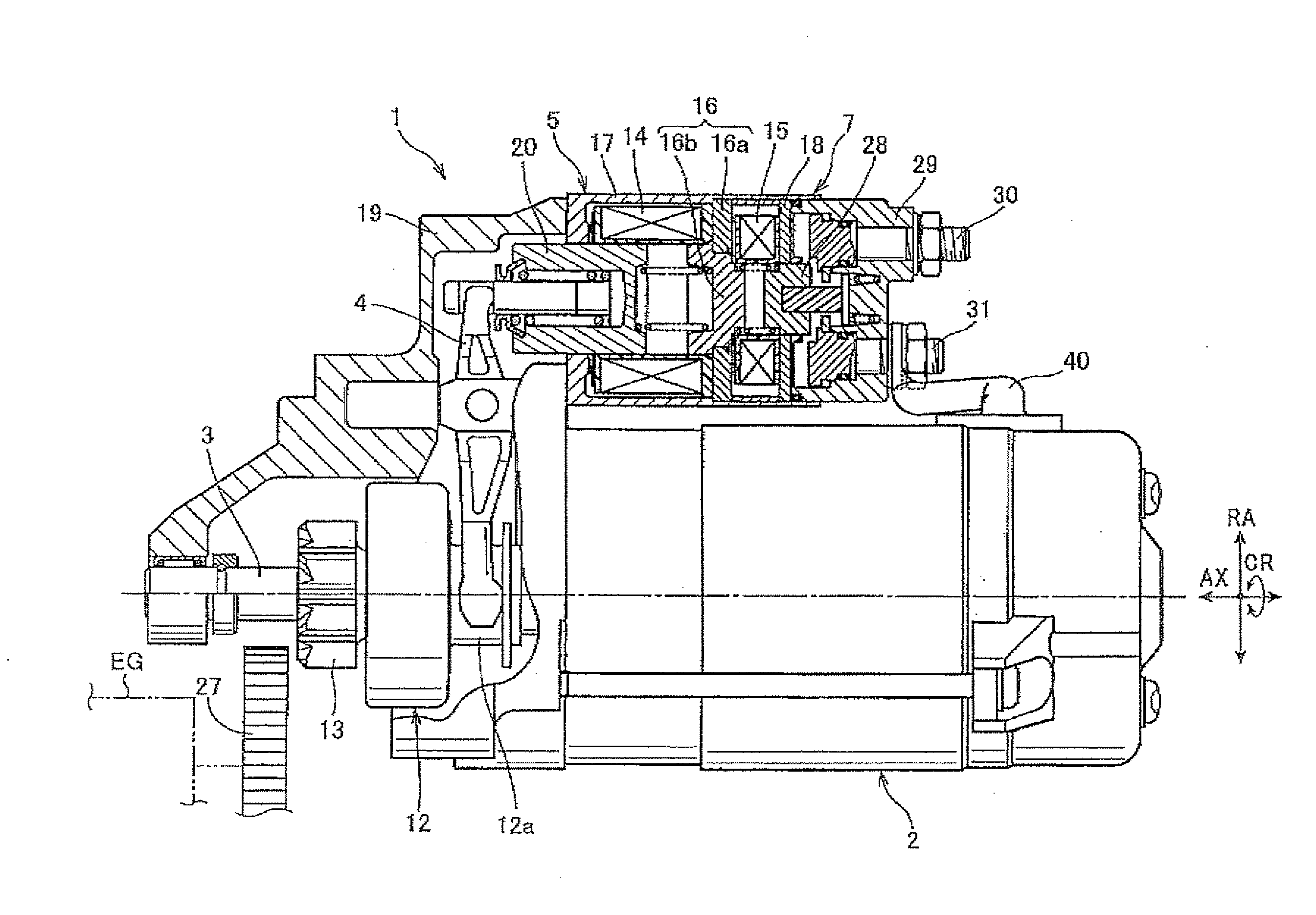
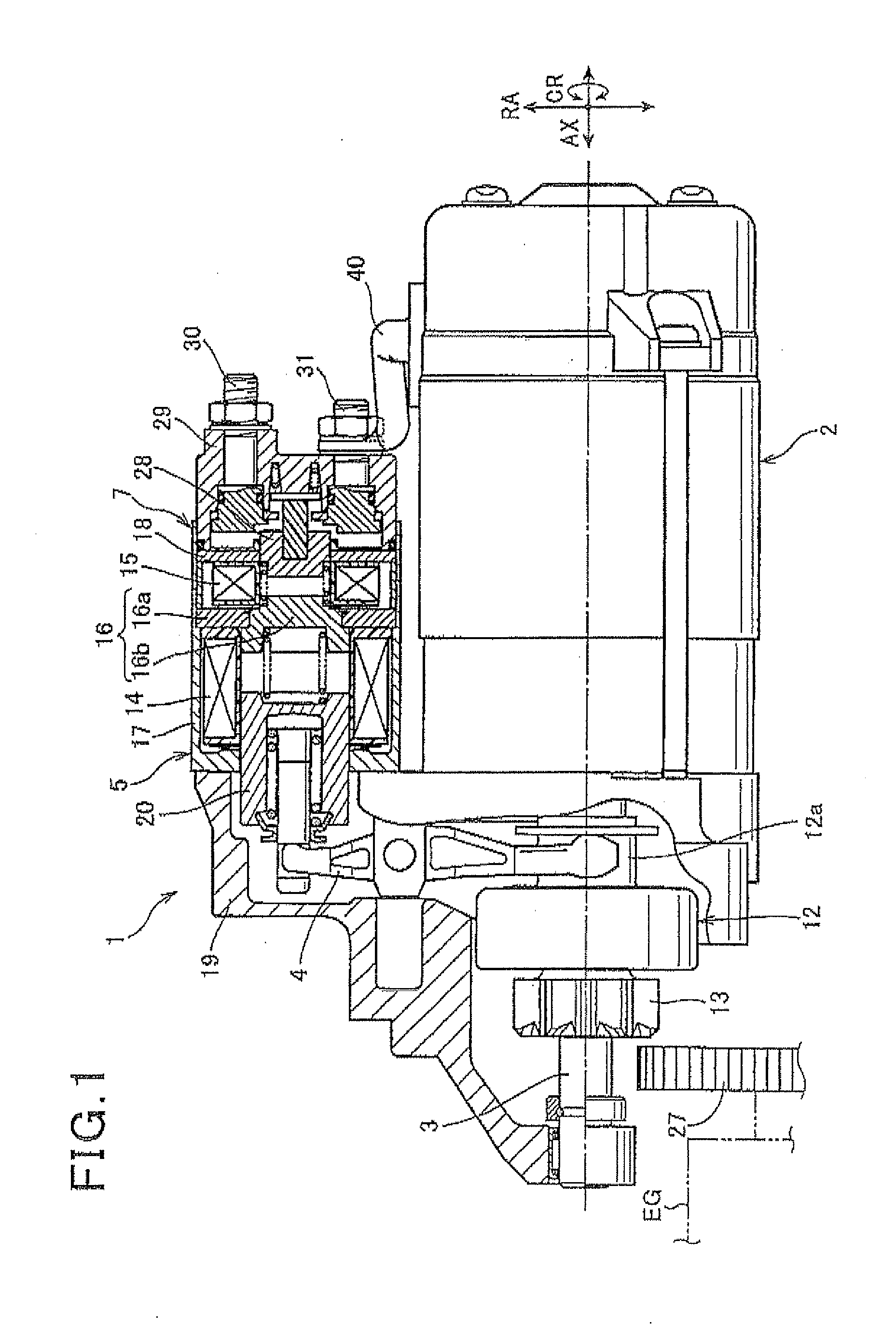
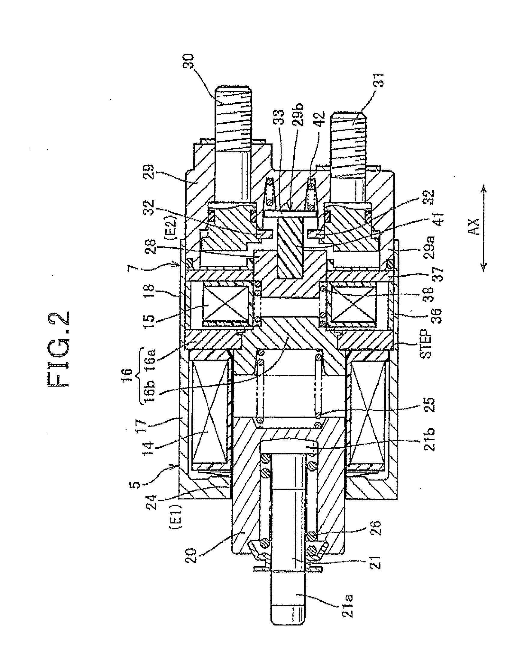
[0027]Referring to FIGS. 1 to 3, an apparatus for starting an on-vehicle engine according to a first embodiment of the present invention will be described.

[0028]The apparatus for starting the engine of the first embodiment includes a starter 1 that starts an on-vehicle engine EG. FIG. 1 is a cross-sectional view illustrating the starter 1. In the first embodiment, the apparatus for starting the engine EG is loaded in a vehicle having an idle stop system. For example, the idle stop system is able to automatically stop the engine EG when the vehicle is in pause at an intersection by a stop signal or in pause due to traffic jam or the like.

[0029]As shown in FIG. 1, the starter 1 includes a motor 2, an output shaft 3, a shift lever 4, a pinion movable body (described later), pinion-pushing solenoid 5, a battery (see FIG. 3) and a motor electrification switch 7. In the present embodiment, the output shaft has a longitudinal direction, so that directions along the longitudinal direction c...

second embodiment

[0076]Referring now to FIG. 4, hereinafter is described an apparatus for starting an on-vehicle engine according to a second embodiment of the present invention.

[0077]In the second and the subsequent embodiments as well as in the modifications provided below, the components identical with or similar to those in the first embodiment are given the same reference numerals for the sake of omitting explanation.

[0078]The second embodiment is associated with prolonging lives of the contacts used in the starter relay 23 and the motor relay 53 described in the first embodiment.

[0079]Since the configurations of the starter 1 and the solenoid unit (the pinion-pushing solenoid 5 and the motor electrification switch 7) are the same as those in the first embodiment, the explanation Is omitted.

[0080]The solenoid coil 14 of the first embodiment has not been formed of two coils, an attraction coil and a holding coil. Instead, the solenoid coil 14 of the first embodiment has been formed of a single c...

third embodiment

[0088]Referring to FIGS. 5 to 7, an apparatus for starting an on-vehicle engine according to a third embodiment of the present invention is described.

[0089]The third embodiment is different from the first and second embodiments in that a tapered projection 20a is provided at the plunger 20 of the pinion-pushing solenoid 5.

[0090]FIG. 5 is a cross-sectional view illustrating a solenoid unit of the third embodiment. As shown in FIG. 5, the plunger 20 of the pinion-pushing solenoid 5 is provided with the projection 20a having a tapered shaped. Specifically, the plunger 20 has an end face, in a radially inner side of which the tapered projection 20a is provided being projected to and axially opposed to the core portion 16b. Meanwhile, the core portion 16b has an axial end face in which a tapered recess 16c is formed so that the projection 20a of the plunger 20 can be fitted thereto when the plunger 20 has been attracted to the core portion 16b.

[0091]Building up the plunger 20 by providi...


PUM


Abstract

In a starter for starting an on-vehicle engine, a solenoid is provided to push a pinion gear. The solenoid has an electromagnetic coil composed of a single coil and electrically separated from a motor circuit, a fixed core, and a plunger. Supply of excitation current to the electromagnetic coil allows the fixed core to be magnetized to attract the plunger. Hence, a movement of the plunger results in a push of the movable member toward the ring gear. A switch is provided in the circuit and has a contact, a movable core, and a switch coil functioning as an electromagnet attracting the movable core in response to supply of current to the switch coil. A movement of the movable core results in on/off switching operations of the switch. The switch is allowed to operate independently of the solenoid when both the switch and solenoid are controlled.

Description

CROSS-REFERENCE TO RELATED APPLICATION[0001]This application is based on and claims the benefit of priority from earlier Japanese Patent Application Nos. 2009-102214 filed Apr. 20, 2009, 2009-281589 filed Dec. 11, 2009, 2010-9832 filed Jan. 20, 2010, and 2010-092197 flied Apr. 13, 2010, the description of which is incorporated herein by reference.BACKGROUND OF THE INVENTIONTechnical Field of the InventionRelated Art[0002]In vehicles with engines (i.e., internal combustion engines), a starter is usually used to start the engines. Though a variety of types of starters are known, one type of such starters is provided with a magnet field type of electric motor having an armature and a field coil, a solenoid, and a switch. The solenoid is used to push, using a shift lever, a pinion gear toward a ring gear attached to an on-vehicle engine. The switch turns on / off a main contact arranged in an electric circuit for driving the motor (known as a motor circuit), in which the motor circuit dri...

Claims


Application Information

Patent Timeline
IPC IPC(8): H02K11/00
CPCF02N11/087Y10T74/134F02N15/067F02N2011/0892H01H51/065
Inventor HARUNO, KIYOKAZUMURATA, MITSUHIROSAITO, MIKIONIIMI, MASAMI
Owner DENSO CORP
Why Eureka
Try Eureka