Pre-connectorized fiber optic distribution cable having overmolded access location

a technology access location, which is applied in the field of pre-connectorized can solve the problems of affecting the quality of fiber optic distribution cable, etc., and achieves the effect of reducing the difference in the length of the span

Active Publication Date: 2006-05-04
CORNING CABLE SYST LLC +1
View PDF18 Cites 127 Cited by
  • Summary
  • Abstract
  • Description
  • Claims
  • Application Information

AI Technical Summary

Benefits of technology

[0011] In one embodiment, the present invention provides a pre-connectorized fiber optic distribution cable assembly comprising a distribution cable having a plurality of optical fibers and at least one mid-span access location positioned along the length of the distribution cable. At least one optical fiber of the distribution cable is accessed and terminated from the distribution cable at the mid-span access location. The assembly further comprises at least one optical connector mounted upon the end of the accessed and terminated optical fiber, a receptacle for receiving the optical connector and providing access to the optical connector without entering the mid-span access location, and a protective overmolded shell formed from a relatively flexible material encapsulating the mid-span access location and securing the receptacle within the shell. The assembly may further comprise a tether having a customized length that is pre-connectorized and interconnected in the field with the optical connector disposed within the receptacle. The tether is operable for mitigating errors in the actual location of the mid-span access along the length of the installed distribution cable, and in particular, span length measurement differences in a pre-engineered fiber optic communications network.
[0013] In a farther embodiment, the present invention provides a method for mitigating a span length measurement difference in a pre-engineered fiber optic communications network employing a fiber optic distribution cable assembly comprising a distribution cable having a plurality of optical fibers disposed within a sheath and at least one mid-span access location. The method comprises removing a section of the sheath of the distribution cable at the mid-span access location, accessing at least one of the plurality of optical fibers of the distribution cable within the sheath of the distribution cable, terminating the at least one optical fiber accessed from within the removed section of the sheath, connectorizing the at least one optical fiber, overmolding the mid-span access location such that the connectorized optical fiber is accessible for subsequent interconnection with a connectorized optical fiber mounted on a first end of a tether, installing the distribution cable assembly in the pre-engineered fiber optic communications network, optically connecting the connectorized first end of the tether to the connectorized optical fiber of the distribution cable at the mid-span access location, and positioning a second end of the tether opposite the first end at a desired location to compensate for the span length measurement difference.
[0014] In a still further embodiment, the present invention provides a pre-connectorized fiber optic distribution cable for use in a pre-engineered optical communications network. The pre-connectorized distribution cable comprises a plurality of predetermined mid-span access locations along the length of the distribution cable that provide access to at least one terminated and pre-connectorized optical fiber disposed within a receptacle through a low-profile, relatively flexible overmolded shell that encapsulates the mid-span access location and the receptacle. The pre-connectorized distribution cable may be readily deployed in the pre-engineered optical communications network in a factory-assembled configuration to be interconnected with at least one fiber optic drop cable leading to a subscriber premises, or with a fiber optic branch cable or tether leading to a network optical connection terminal.

Problems solved by technology

In addition, in order to reduce installation labor costs in FTTx networks, communications service providers are increasingly demanding factory-prepared interconnection solutions, commonly referred to as “plug-and-play” type systems.
The relatively difficult and time consuming process of creating the mid-span access, however, must be accomplished by a highly skilled technician at a significant cost and under less than ideal field working conditions.
One disadvantage of this approach is that the drop cables and the relatively bulky and inflexible splice closures are attached to the distribution cable prior to installation.
Accordingly, installation through small diameter conduits and over sheave wheels and pulleys is substantially more difficult, and sometimes impossible.
Another disadvantage is the fact that if a mid-span access location is unused following installation, the expensive and obtrusive splice closure and drop cables remain attached to the distribution cable.
As a result, improper location of the mid-span access location due to differences between the pre-engineered span length measurement and the actual span length measurement following installation of the distribution cable can only be mitigated using the predetermined length of drop cable provided from the factory.
Such differences, referred to herein as “span length measurement differences” typically result from network measurement miscalculations, installation errors, and differences between the proposed locations of telephone poles, hand holes, pedestals, etc. and their installed locations.
If the mid-span access location on the installed distribution cable is located too far from the desired location, the drop cable may not have sufficient length.
On the other hand, if the mid-span access location on the installed distribution cable is located too near the desired location, an excessive amount of drop cable slack must be managed.
However, there are disadvantages as well.
While terminating and preparing splice-ready optical fibers in the factory significantly reduces the amount of labor required to connect subscribers to a mid-span access location, it is still necessary to splice the optical fibers of the distribution cable to the optical fibers of the drop cables in the field, oftentimes at an inconvenient location or under less than ideal working conditions.
Another disadvantage is that a relatively expensive splice closure must be added to the distribution cable assembly at the mid-span access location in the field to protect the optical splices and the exposed section of the distribution cable, thereby increasing installation complexity as well as labor and material costs.

Method used


Image

  • Pre-connectorized fiber optic distribution cable having overmolded access location
  • Pre-connectorized fiber optic distribution cable having overmolded access location
  • Pre-connectorized fiber optic distribution cable having overmolded access location

Examples


first embodiment

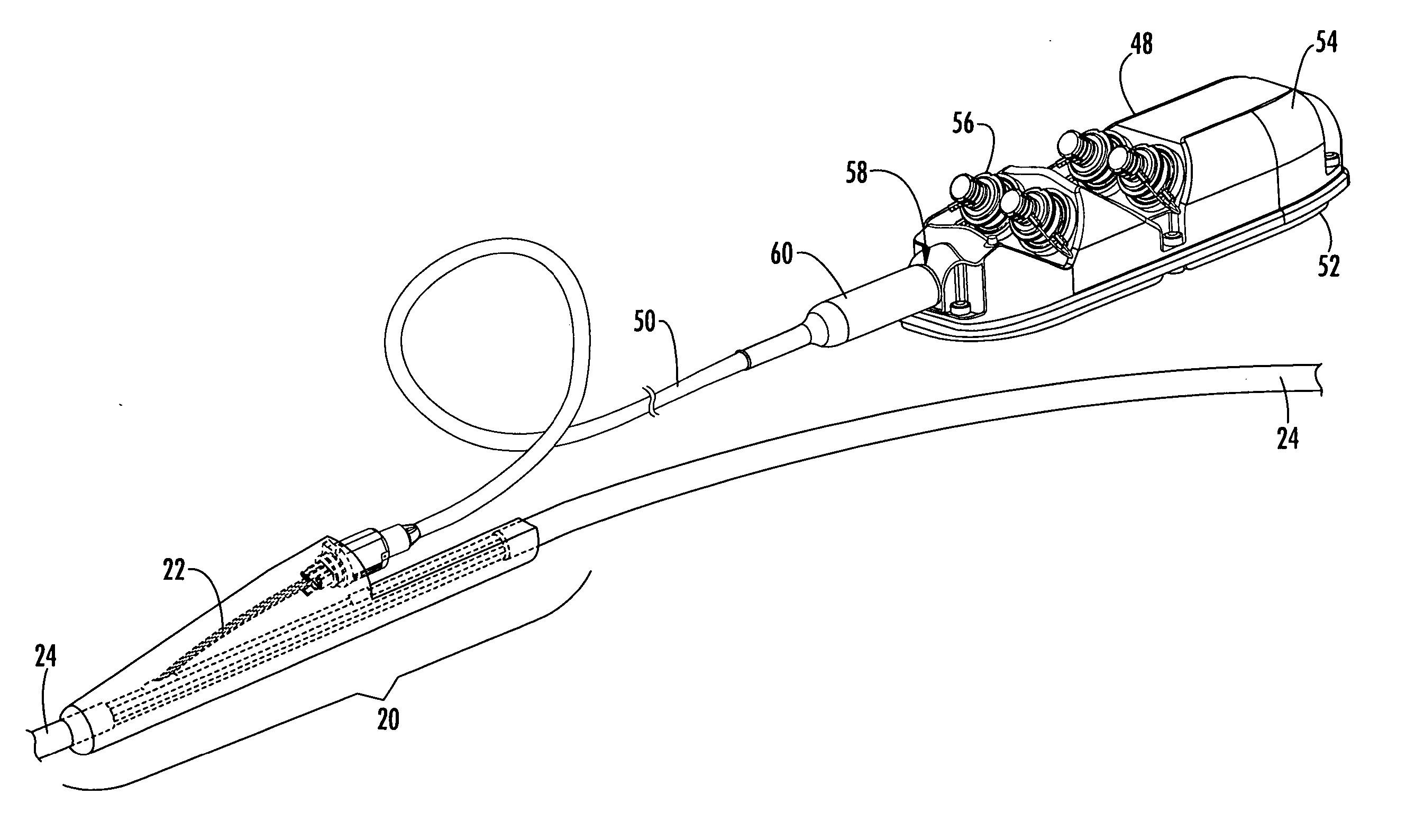
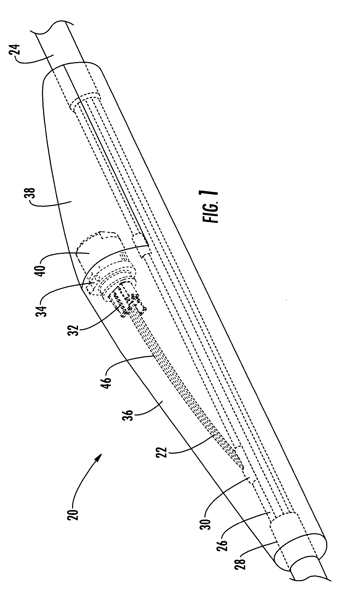
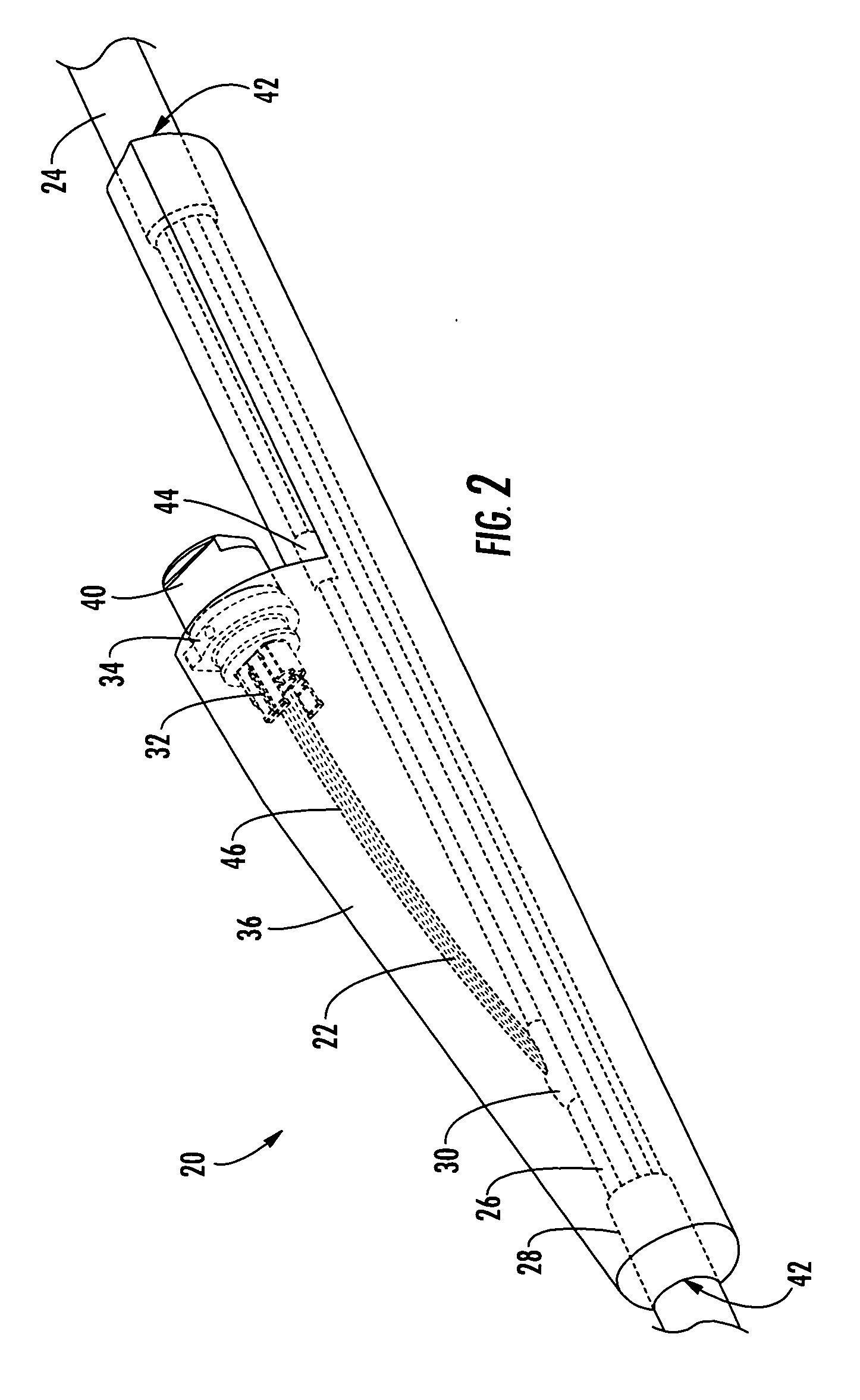
[0039] Referring now to FIG. 3, the distribution cable assembly having a mid-span access location 20 is shown with a multi-port connection terminal 48 optically connected to the distribution cable 24 through the receptacle 34. The mid-span access location 20 provides a means for optically connecting one or more optical fibers contained within a tether 50 to the one or more terminated optical fibers 22 of the fiber optic distribution cable 24. As used herein, the term “tether” is intended to include any fiber optic cable or tubular body having one or more optical fibers contained within the tubular body. The remaining optical fibers of the distribution cable 24 are managed and routed separately from the terminated optical fibers 22 such that they extend uninterrupted through the distribution cable 24 and are available for terminating at other downstream mid-span access locations 20. The tether 50 may have a predetermined length ranging from several feet to several thousand feet that ...

second embodiment

[0042] Referring now to FIG. 4, a perspective view of a typical mid-span access location 20 having a tether 50 attached to the distribution cable 24 that terminates in a multi-port connection terminal 60 is shown. In this embodiment, the multi-port connection terminal 60 is overmolded, thereby eliminating access to the optical fibers of the tether 50 and the optical connection ports 56 within the multi-port connection terminal 60 for repair or replacement. The overmolded multi-port connection terminal 60 includes the advantages of overmolding previously described, while still providing external access to one or more connectorized optical fibers of the tether 50 that are optically connected to the terminated optical fibers 22 of the distribution cable 24 through the ferrule 32 disposed within the receptacle 34 located at the mid-span access location 20. The overmolded multi-port connection terminal 60 may be used to readily interconnect optical fibers of one or more connectorized fib...


PUM


Abstract

A pre-connectorized fiber optic distribution cable assembly includes a plurality of optical fibers and at least one mid-span access location along the length of the distribution cable. At least one of the optical fibers is accessed, terminated and then connectorized at the mid-span access location to an optical connector disposed within a receptacle. The mid-span access location, the accessed, terminated and connectorized optical fiber, the optical connector and at least a portion of the receptacle are encapsulated with a protective overmolded shell. A tether including at least one optical fiber connectorized at a first end of the tether is optically connected to the optical connector through the receptacle. A second end of the tether opposite the first end terminates in a network optical connection terminal, thereby compensating for a span length measurement difference between the actual location of the mid-span access and the desired location of the optical connection terminal.

Description

BACKGROUND OF THE INVENTION [0001] 1. Field of the Invention [0002] The present invention relates generally to a pre-connectorized fiber optic distribution cable and, more particularly, to a pre-connectorized fiber optic distribution cable having an overmolded mid-span access location that compensates for span length measurement differences. [0003] 2. Description of the Related Art [0004] Optical fiber is increasingly being used for a variety of broadband applications including voice, video and data transmissions. As a result, there is a need for connecting remote locations to a fiber optic distribution cable in order to provide broadband services to an end user, commonly referred to as a subscriber. In this regard, fiber optic networks are being developed that deliver “fiber-to-the-curb” (FTTC), “fiber-to-the-business” (FTTB), “fiber-to-the-home” (FTTH) and “fiber-to-the-premises” (FTTP), referred to generically as “FTTx.” networks. To provide these services to the subscriber, FTTx...

Claims


Application Information

Patent Timeline
Patent Type & Authority Applications(United States)
IPC IPC(8): G02B6/36G02B6/00
CPCG02B6/4473G02B6/4495G02B6/4431
Inventor ELKINS, ROBERT B. IITHEUERKORN, THOMASNIELSEN, LARS K.LUTHER, JAMES P.
Owner CORNING CABLE SYST LLC
Why Eureka
Try Eureka