
Magnetically stabilized forward observation platform

a forward observation platform and magnetic stabilizer technology, applied in the direction of navigation instruments, instruments, using reradiation, etc., can solve the problems of inability to develop targets, lack of accurate azimuth and elevation angles, and light weight of simple range finders, so as to improve the speed of initialization and operation

Active Publication Date: 2012-09-25
GENERAL ATOMICS
View PDF15 Cites 252 Cited by
  • Summary
  • Abstract
  • Description
  • Claims
  • Application Information

AI Technical Summary

Benefits of technology

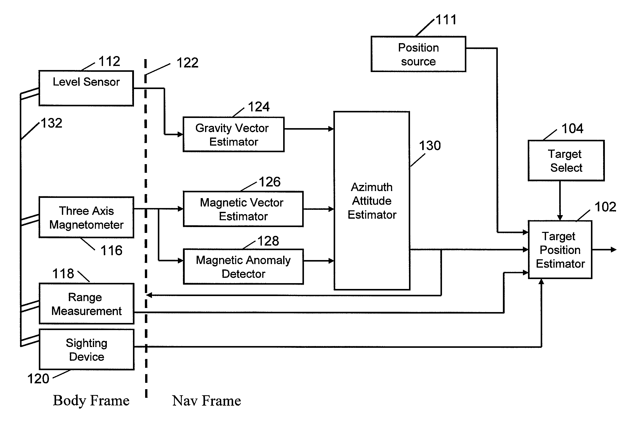
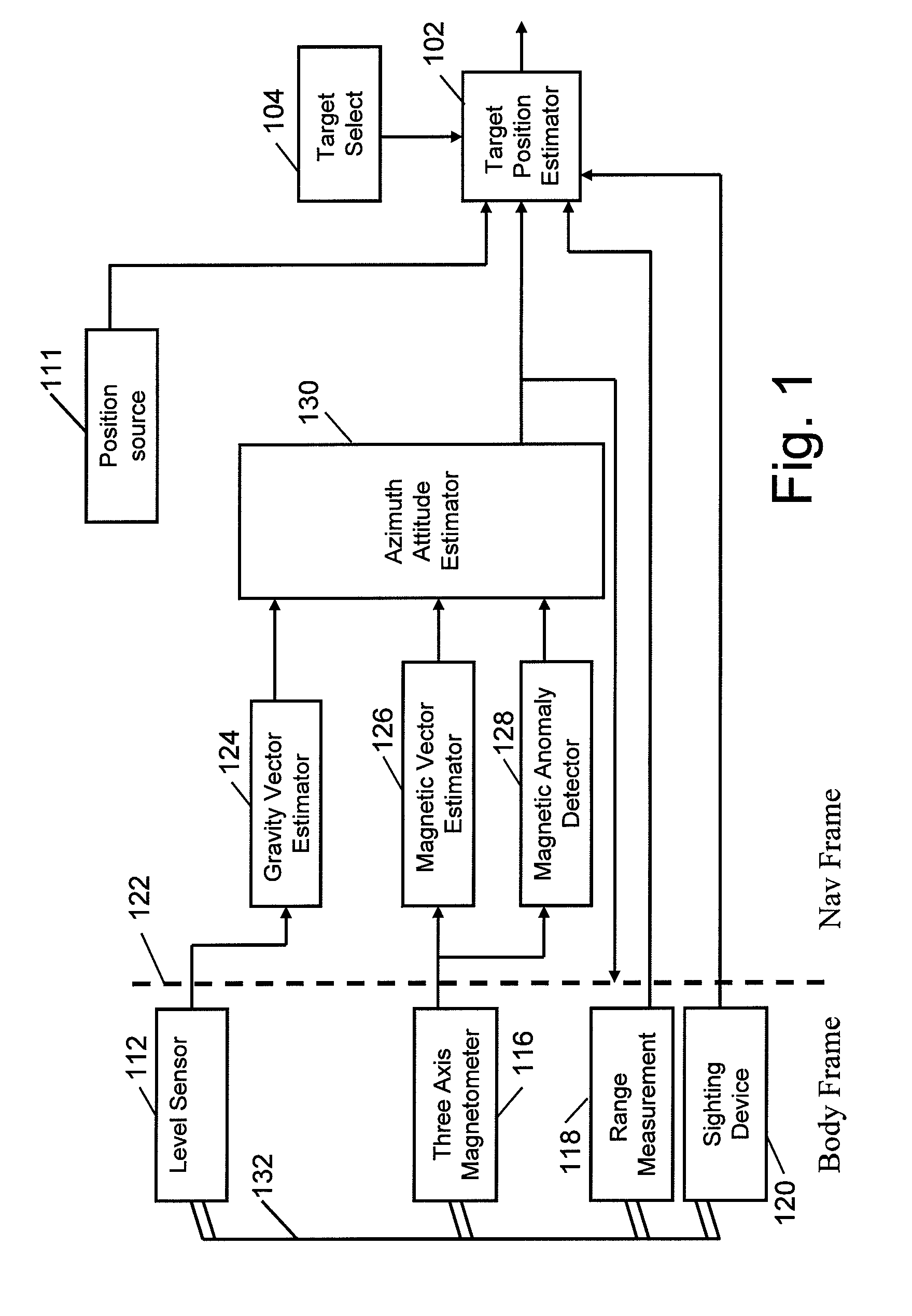
[0004]Briefly, the disclosed embodiments relate to a system and method for determining a position of a remote object comprising a compact, relatively low performance inertial measurement unit compensated by a three axis magnetic sensor in combination with a GPS receiver for determining an observation platform position and orientation. A target sighting device determines a line of sight vector to the target, and in one embodiment, a range finder determines range. The three axis magnetic sensor provides both magnetic north and attitude information for improved rapid initialization and operation while the observation platform is in motion. Magnetic anomaly information is detected by comparing IMU and magnetic navigation information. Target identification may be determined by a human operator and / or by computer. The system may be integrated with a weapon system to use weapon system sights. The system may be networked to provide target location and / or location error information to another identical unit or a command information system.
[0005]In one aspect, embodiments of the system may use a low cost Micro-Electro-Mechanical System (MEMS) Inertial Measurement Unit (IMU) comprising a three axis MEMS rate gyro triad and a three axis MEMS accelerometer triad. Rate gyro bias errors in both azimuth and elevation may be reduced by observing the three axis magnetic sensor information.

Problems solved by technology

Simple range finders are light weight, often resembling binoculars, but lack the ability to determine accurate azimuth and elevation angles or to communicate target information.
Typical command fire units for weapons such as shoulder launched missiles may include an embedded range finder, and are adequate for acquisition track and launch, but do not have the ability to develop target coordinate information and to communicate that information to other units for coordinated firing or intelligence activities.
The technologies typically employed in target location devices typically result in large, heavy units that preclude integration with light weapons like shoulder launched missiles.
Both systems are very heavy tripod mounted device weighing over 50 kg, far to cumbersome to integrate with small weapons like shoulder fired weapons or to be operated from a free standing position.

Method used


Image

  • Magnetically stabilized forward observation platform
  • Magnetically stabilized forward observation platform
  • Magnetically stabilized forward observation platform

Examples


Embodiment Construction

[0052]It has been recognized that there is a need for a target position measuring device that may be operated on the move or from a free standing position. The device should be light weight enough to be integrated into soldier carried equipment without overburdening and low cost enough to afford wide distribution and use.

[0053]Disclosed is a system and method that enables accurate remote target position determination using a light weight, low cost, navigation unit together with a directed range finder. The system utilizes a three axis magnetic sensor in combination with a level sensor to determine elevation attitude in the presence of lateral accelerations that can disrupt gravitational level measurements alone. With the addition of rate gyros, the three axis magnetic sensor may further stabilize bias errors in the gyros to enable accurate pointing angle measurement of a target sighting device and rangefinder. The system may be combined with GPS for additional position and navigatio...


PUM


Abstract

A system and method for determining a position of a remote object comprising inertial sensors and three axis magnetic sensor, together with a target sighting device aligned with the observation platform to determine a target line of sight and a target range finder to determine a distance to the target along the line of sight. A GPS receiver may be included for determining an observation platform position and orientation, The three axis magnetic sensor provides both magnetic north and vertical attitude information for improved rapid initialization and operation in motion. Magnetic anomaly information is detected by comparing IMU and magnetic navigation information and by other methods. Target identification may be determined by a human operator and / or by computer. The system may be integrated with a weapon system to use weapon system sights. The system may be networked to provide target location and / or location error information to another identical unit or a command information system.

Description

RELATED APPLICATIONS[0001]This application is a continuation-in-part of prior U.S. patent application Ser. No. 11 / 285,644 entitled: “Inertial / Magnetic Measurement Device” filed Nov. 21, 2005 now U.S. Pat. No. 7,587,277 by Wells, the contents of which are hereby incorporated herein by reference in their entirety.FIELD OF THE INVENTION[0002]The disclosed embodiments pertain generally to the field of remote target position determination and mapping, more particularly to a system and method of using a three axis magnetic sensor to enable accurate target positioning using a miniature IMU and rangefinder.BACKGROUND OF THE INVENTION[0003]Currently, target location devices fall into three categories, independent units, integrated command fire units (CFU), and simple range finders. The independent units are typically heavy units requiring vehicle or tripod mount for operation. Simple range finders are light weight, often resembling binoculars, but lack the ability to determine accurate azimu...

Claims


Application Information

Patent Timeline
IPC IPC(8): G01C21/02
CPCG01C21/165G01S17/023F41G3/02F41G3/06G01S7/003G01S17/86G01C21/1656G01C21/1654G01C21/1652
Inventor WELLS, RANDY LOUISANDERSON, RUSTY ALLENPINCZEWSKI, II, EUGENE E.OAKLEY, JR., ROBERT EDWARDGESIN, RALPH FRANCISROJAS, RUBEN
Owner GENERAL ATOMICS
Learn More