LED lamp

a technology of led lamps and lampshades, applied in the field of led lamps, can solve the problems of easy production of color unevenness, inevitably produced color unevenness, white light, etc., and achieve the effect of reducing glar

Active Publication Date: 2007-04-17
SOVEREIGN PEAK VENTURES LLC
View PDF11 Cites 118 Cited by
  • Summary
  • Abstract
  • Description
  • Claims
  • Application Information

AI Technical Summary

Benefits of technology

[0013]In order to overcome the problems described above, preferred embodiments of the present invention provide an LED lamp that can reduce the glare significantly.
[0018]In another preferred embodiment, the LED lamp preferably further includes a resistor, which is connected to at least one of the first and second interconnection patterns. The resistor preferably reduces a difference between the amounts of currents flowing through the first and second interconnection patterns.
[0023]An LED lamp according to any of various preferred embodiments of the present invention described above can control the amount of light emitted from LEDs located around the outer periphery and the amount of light emitted from LEDs located elsewhere independently of each other. Thus, the luminance of the outer LEDs, which changes the degree of glare significantly, can be controlled selectively. As a result, the glare can be reduced effectively.

Problems solved by technology

An LED lamp of this type, however, easily produces color unevenness because the LED of each color has an excellent monochromatic peak.
That is to say, unless the light rays emitted from the respective LEDs are mixed together uniformly, color unevenness will be produced inevitably in the resultant white light.
However, the luminous flux of a single LED is too low.
As a result, the unwanted color unevenness is produced.
However, the present inventors further analyzed this LED lamp 300 to discover that the LED lamp 300 with such a high luminous flux (which is sometimes called a “high-flux LED lamp”) often produces an uncomfortable glaring impression on the viewer although everybody in the prior art has been paying most of their attention to how to increase the luminous flux of the LED lamp.
Accordingly, it is believed that the viewer is very likely to find an LED lamp glaring if the LED lamp includes a plurality of LEDs, has a high luminance, and is used in a relatively dark place.
Nevertheless, if the luminance of the LED lamp were decreased to reduce such a glare, then the LED lamp would be too dark to use as general illumination.

Method used


Image

  • LED lamp
  • LED lamp
  • LED lamp

Examples


embodiment 1

[0063

[0064]First, an LED lamp 100 according to a first specific preferred embodiment of the present invention will be described with reference to FIGS. 10 and 11.

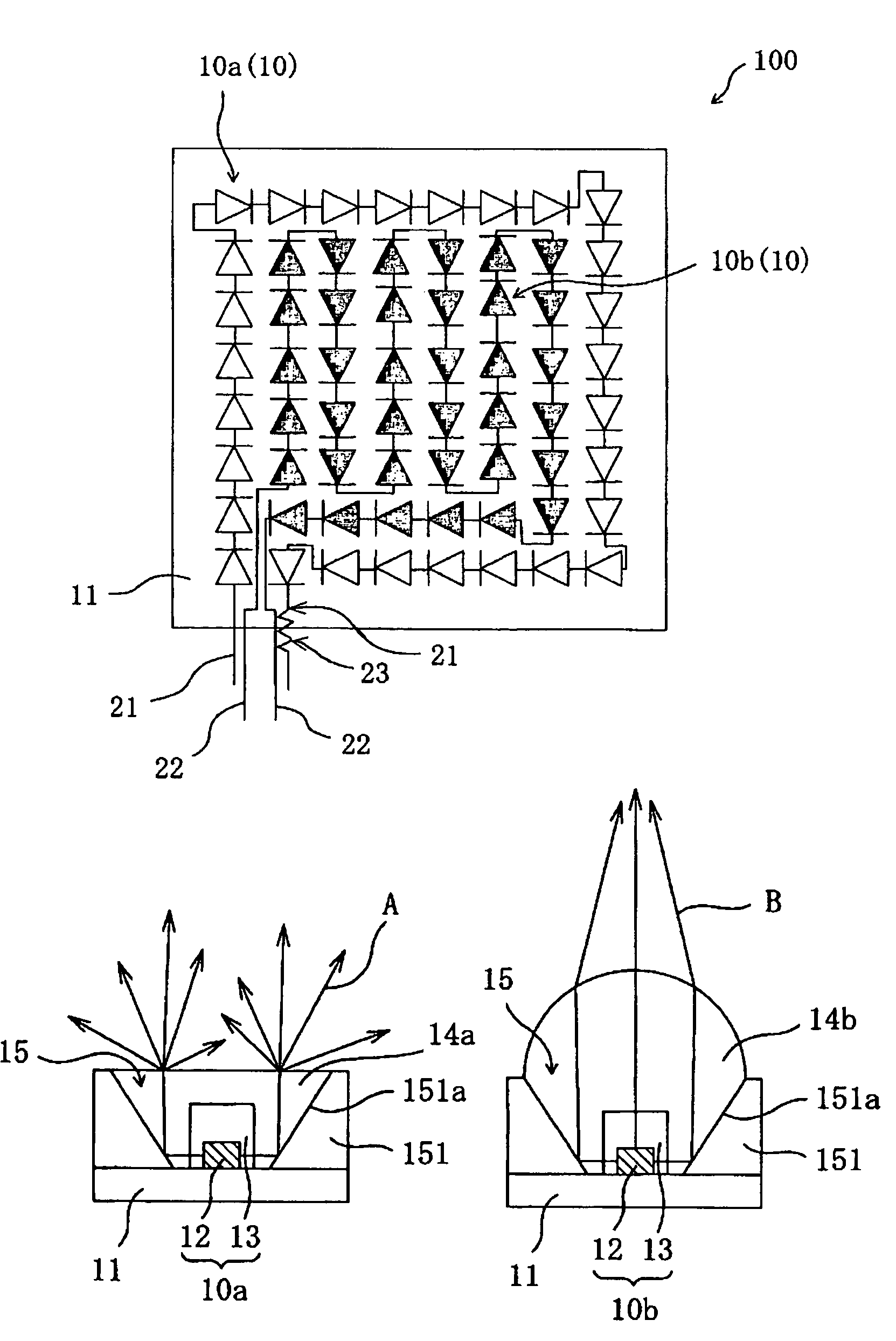
[0065]FIG. 10 schematically shows an arrangement for the LED lamp 100. As shown in FIG. 10, the LED lamp 100 includes a substrate 11, a plurality of LEDs 10 arranged two-dimensionally on the substrate 11, and an interconnection circuit 20 that is electrically connected to the LEDs 10.

[0066]The LEDs 10 make up a cluster of LEDs that are densely arranged two-dimensionally. The LEDs 10 included in that LED cluster are roughly classified into the two groups. Specifically, a first group consists of the LEDs 10a that are located in the outside portion of the cluster, while a second group consists of the LEDs 10b that are located in the inside portion of the cluster.

[0067]The interconnection circuit 20 of this preferred embodiment includes a first interconnection pattern 21 and a second interconnection pattern 22, which is provide...

embodiment 2

[0101

[0102]Hereinafter, an LED lamp according to a second specific preferred embodiment of the present invention will be described.

[0103]In the LED lamp 100 of the first preferred embodiment described above, the amount of the light emitted from the outer LEDs 10a is controlled appropriately, thereby reducing the glare effectively. In this preferred embodiment, an arrangement for further reducing the glare is adopted.

[0104]FIGS. 22A and 22B schematically illustrate a configuration for a lens 14a that covers the outer LED 10a and a configuration for a lens 14b that covers the inner LED 10b, respectively. As shown in FIGS. 22A and 22B, in this preferred embodiment, the inner lens 14b has a lens structure that forms a narrower luminous intensity distribution than the outer lens 14a does. By adopting such an arrangement, even if the amount of the light emitted from the outer LEDs 10a has been decreased, it is harder for the light emitted from the inner LEDs 10b to diffuse outward due to ...


PUM


Abstract

An LED lamp includes: a substrate; a cluster of LEDs, which are arranged two-dimensionally on the substrate; and an interconnection circuit, which is electrically connected to the LEDs. The LEDs include a first group of LEDs, which are located around the outer periphery of the cluster, and a second group of LEDs, which are located elsewhere in the cluster. The interconnection circuit has an interconnection structure for separately supplying drive currents to at least one of the LEDs in the first group and to at least one of the LEDs in the second group separately from each other.

Description

BACKGROUND OF THE INVENTION[0001]1. Field of the Invention[0002]The present invention relates to an LED lamp and more particularly relates to a white LED lamp that can be used as general illumination.[0003]2. Description of the Related Art[0004]A light emitting diode (LED) is a semiconductor device that can radiate an emission in a bright color with high efficiency even though its size is small. The emission of an LED has an excellent monochromatic peak. To obtain white light from LEDs, a conventional LED lamp arranges red, green and blue LEDs close to each other and gets the light rays in those three different colors diffused and mixed together. An LED lamp of this type, however, easily produces color unevenness because the LED of each color has an excellent monochromatic peak. That is to say, unless the light rays emitted from the respective LEDs are mixed together uniformly, color unevenness will be produced inevitably in the resultant white light. Thus, to overcome such a color ...

Claims


Application Information

Patent Timeline
Patent Type & Authority Patents(United States)
IPC IPC(8): F21V9/00F21K99/00F21L4/02F21S6/00F21V19/00H05B44/00
CPCF21K9/00F21S6/003H05B33/0803H05B33/0815H05B33/0821H05B33/0842H05B33/0857F21L4/027F21S6/00F21V19/001F21Y2101/02F21Y2115/10H05B45/40H05B45/20H05B45/37
Inventor YANO, TADASHISHIMIZU, MASANORI
Owner SOVEREIGN PEAK VENTURES LLC
Why Eureka
Try Eureka