Light emitting diode driving module

a technology of light-emitting diodes and driving modules, which is applied in the direction of instruments, light sources, electroluminescent light sources, etc., can solve the problems of serious electromagnetic interference (emi), non-uniform luminance as a whole, and inability to solve economic solutions, etc., to achieve the effect of increasing the light-emitting efficiency and luminance uniformity of led strings

Inactive Publication Date: 2009-10-22
NOVATEK MICROELECTRONICS CORP
View PDF6 Cites 116 Cited by
  • Summary
  • Abstract
  • Description
  • Claims
  • Application Information

AI Technical Summary

Benefits of technology

[0008]Accordingly, the present invention is directed to an LED driving module for dynamically adjusting the voltage and current of driving an LED string so as to thereby increase the light-emitting efficiency and luminance uniformity of the LED strings.

Problems solved by technology

However, the LEDs served as the light source of a backlight module of a display panel confront two stubborn problems.
One of the problems is how to make a plurality of light emitting diode strings (LED strings) in a backlight module produce uniform luminance so as to have better display effect with a display panel.
Once only a fixed voltage is used to drive different LED strings, the characteristic difference between individual LED strings would result in nonuniform luminance as a whole.
Although the above-mentioned scheme is able to individually adjust luminance of each of the LED strings to effectively overcome the problem resulted by the characteristic difference between the LED strings, but the conventional scheme requires a numerous voltage-to-current converters, which is not economical solution.
The frequent switching of the switches tends to produce inrush currents leading to serious electromagnetic interference (EMI).

Method used


Image

  • Light emitting diode driving module
  • Light emitting diode driving module
  • Light emitting diode driving module

Examples


first embodiment

The First Embodiment

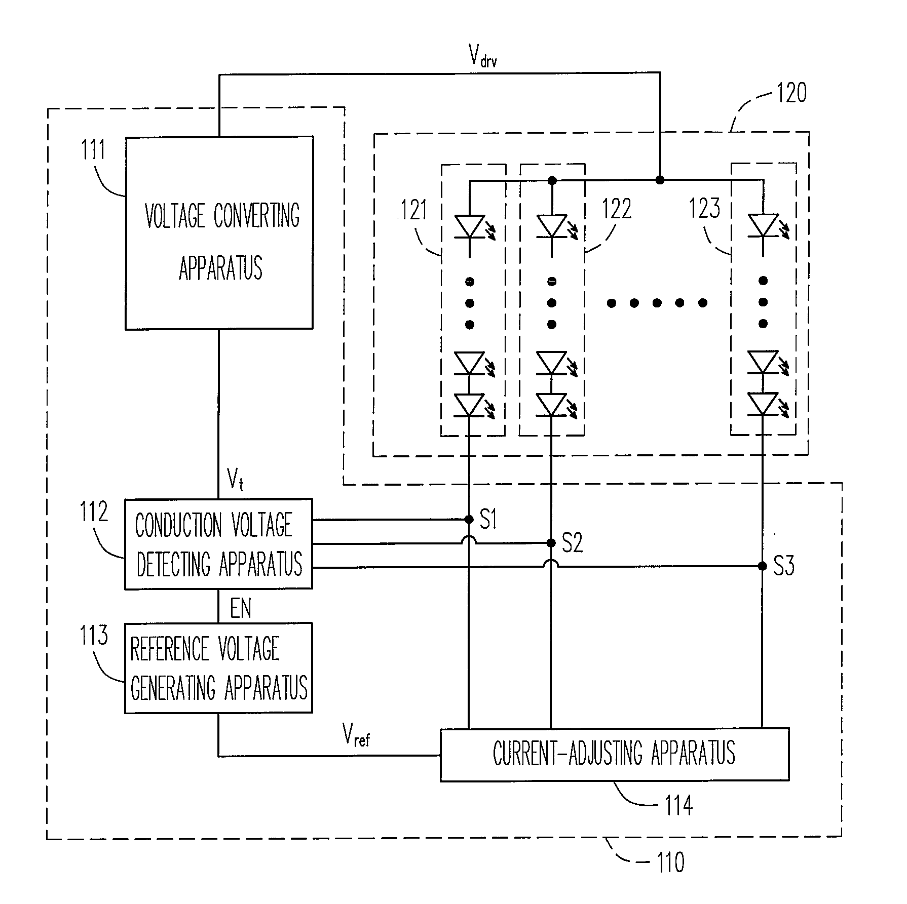
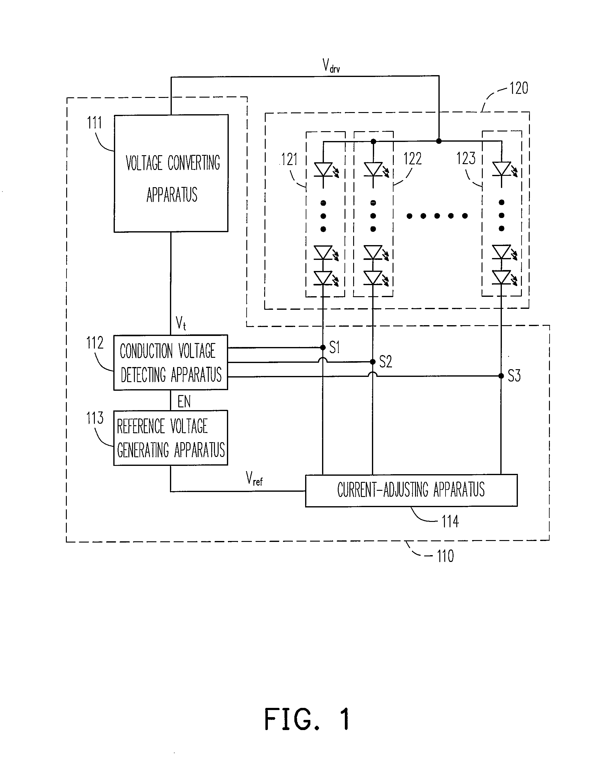
[0021]FIG. 1 is a circuit diagram of an LED driving module according to the first embodiment of the present invention. Referring to FIG. 1, the LED driving module 110 is for driving a plurality of LED strings 120 in parallel connection. The LED driving module 110 includes a voltage converting apparatus 111, a conduction voltage detecting apparatus 112, a reference voltage generating apparatus 113 and a current-adjusting apparatus 114.

[0022]The voltage converting apparatus 111 is for producing driving voltages Vdrv of a set of LED strings 120 consisted of LED strings 121-123. Usually, the voltage converting apparatus 111 can be implemented by a DC-to-DC converter based on voltage-boosting or a charge pump. No matter which of the above-mentioned circuit is used, the voltage converting apparatus 111 needs to uses a feedback voltage Vt as a reference voltage for voltage-boosting. The driving voltage Vdrv is a multiple of the feedback voltage Vt (the multiple herein i...

second embodiment

The Second Embodiment

[0046]The present invention also provides the second embodiment for anyone skilled in the art to further understand the spirit of the present invention.

[0047]FIG. 6 is a circuit diagram of an LED driving module according to the second embodiment of the present invention. Referring to FIG. 6, differentially from the first embodiment, in the second embodiment, an additional current-balancing device 630 is employed and the implement of the current-adjusting apparatus 614 is also modified from that of the first embodiment.

[0048]In terms of the implement of the current-adjusting apparatus 614, to avoid the driving current sources of the set of LED strings 620 from directly outputting a large driving current, the second embodiment uses a scheme of amplifying current stage by stage. That is, the current amplifier 616 produces a basic current according to the voltage at the positive terminal of the amplifier 640, wherein the basic current can be also adjusted by an adju...


PUM


Abstract

An LED driving module suitable to drive a plurality of LED strings in parallel connection is disclosed. The LED driving module includes a voltage converting apparatus, a conduction voltage detecting apparatus, a reference voltage generating apparatus and a current-adjusting apparatus. The voltage converting apparatus produces a driving voltage according to a conduction voltage. The conduction voltage detecting apparatus detects the conducting states of the LED strings for producing a conduction voltage and an enabling signal. The reference voltage generating apparatus generates a first reference voltage according to the enabling signal. The current-adjusting apparatus produces a plurality of driving currents according to the first reference voltage, and the driving currents flow through the LED strings.

Description

CROSS-REFERENCE TO RELATED APPLICATION[0001]This application claims the priority benefit of Taiwan application serial no. 97114262, filed on Apr. 18, 2008. The entirety of the above-mentioned patent application is hereby incorporated by reference herein and made a part of specification.BACKGROUND OF THE INVENTION[0002]1. Field of the Invention[0003]The present invention generally relates to a light emitting diode module (LED module), and more particularly, to a driving module for driving an LED.[0004]2. Description of Related Art[0005]Due to low power consumption and high luminance, LEDs have been effectively applied in various applications, for example, illumination light, electronic bulletin board and traffic light. In particular, in display field, LEDs have excellent color performance within the gamut set out by National Television Standard Committee (NTSC); therefore, LEDs are gradually substituting a cold cathode fluorescent lamps (CCFL) employed by a backlight module of a disp...

Claims


Application Information

Patent Timeline
Patent Type & Authority Applications(United States)
IPC IPC(8): H05B37/00H05B41/36
CPCH05B33/0827H05B33/0815H05B45/325H05B45/38H05B45/46
Inventor CHEN, KE-HORNGCHIU, CHIA-LINCHENG, LAN-SHAN
Owner NOVATEK MICROELECTRONICS CORP
Why Eureka
Try Eureka