Check patentability & draft patents in minutes with Patsnap Eureka AI!

Vane pump seal

a technology of valve valve and seal, which is applied in the direction of liquid fuel engines, machines/engines, rotary/oscillating piston pump components, etc., can solve the problems of significant leakage and loss of pump efficiency

Active Publication Date: 2019-01-24
HAMILTON SUNDSTRAND CORP
View PDF2 Cites 0 Cited by
  • Summary
  • Abstract
  • Description
  • Claims
  • Application Information

AI Technical Summary

Benefits of technology

The single seal tube assembly effectively reduces leakage, enhances pump efficiency, and allows for emergency operations by maintaining sealing even during relative motion, ensuring reliable aircraft performance.

Problems solved by technology

The tight clearance can lead to issues, however, arising from thermal growth, misalignment or axial movement of the components noted above or from the occurrence of small contamination particles passing through fuel filters and causing various parts to touch and which can result in galling.
These and other issues can lead to seizure of either of both of the labyrinth seals and a seized labyrinth seal can be a source of significant leakage as well as a loss of pump efficiency.

Method used


Image

  • Vane pump seal
  • Vane pump seal
  • Vane pump seal

Examples


Embodiment Construction

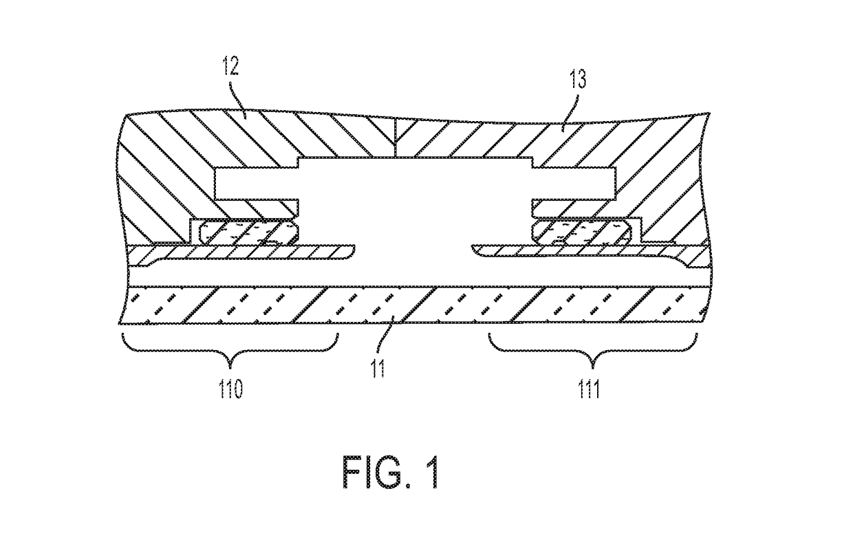
[0034]As will be described below, the two adjacent labyrinth seals described above and their retaining hardware are eliminated from a pump system. A single seal tube is then added to seal first and second vane pumps together. The single seal tube incorporates an internal o-ring and a back-up ring on each end thereof to seal the tube to the vane pumps. During normal operations, the single seal tube rotates at the same velocity as both of the vane pumps and the o-rings completely seal adjacent areas from leakage that previously existed so that axial pressure balance of the rotor is unaffected. The single seal tube and the o-rings can have a design life that meets or exceeds the full service life of the pump system. The quantity of leakage eliminated can then be used to improve pump efficiency or can be applied to provide for additional leakage allowance to remaining labyrinth seals by allowing for an increase in their diametrical clearances and by improving their robustness to failure...


PUM


Abstract

A seal tube assembly of a pump system is provided. The seal tube assembly includes a single seal tube having a first axial end sealably coupled to a first vane pump and a second axial end sealably coupled to a second vane pump. The single seal tube includes transverse contact surfaces at the first axial end and transverse contact surfaces at the second axial end. The single seal tube is formed to define a first seal tube cavity at the first axial end and a second seal tube cavity at the second axial end

Description

CROSS-REFERENCE TO RELATED APPLICATIONS[0001]This application claims the benefit of U.S. patent application Ser. No. 15 / 397,397, filed Jan. 3, 2017. The entire contents of U.S. patent application Ser. No. 15 / 397,397 are incorporated herein by reference.STATEMENT OF FEDERAL SUPPORT[0002]This invention was made with Government support under contact number D6305-L09C-52-00-2100000 awarded by the United States Air Force. The Government has certain rights in the invention.BACKGROUND[0003]The following description relates to a vane pump seal and, more particularly, to a vane pump seal with a single seal tube that incorporated an internal O-ring and has backup rings on each end.[0004]In a pump system of an engine or transmission of an aircraft, for example, first and second vane pump elements are provided for operation about a rotor. Each vane pump typically has two labyrinth seals that seal the spinning rotor to limit leakage from a high pressure region surrounding the rotor outer diamete...

Claims


Application Information

Patent Timeline
Patent Type & Authority Applications(United States)
IPC IPC(8): F04C15/00F16J15/02F04D29/10F04D13/12F04C2/34F04C11/00
CPCF16J15/02F04D29/106F04D13/12F04C2/34F04C15/0023F04C11/001F04C2240/30F04C15/0034F04C2240/806F01C19/005
Inventor CAVIL, LUKE
Owner HAMILTON SUNDSTRAND CORP
Features
  • R&D
  • Intellectual Property
  • Life Sciences
  • Materials
  • Tech Scout
  • Unparalleled Data Quality
  • Higher Quality Content
  • 60% Fewer Hallucinations
Learn More