Optical projection system and devices thereof

Active Publication Date: 2019-05-02
BUENOOPTICS CO LTD
View PDF10 Cites 1 Cited by
  • Summary
  • Abstract
  • Description
  • Claims
  • Application Information

AI Technical Summary

Benefits of technology

[0008]The main objectives of the present invention include: utilizing the combination of the reflector, the reflective curved mirror, and the optical lens to achieve the long-distance virtual imaging in a triangle imaging technique, so as to reduce the necessary volume of the lens; and combining the optical projection system into an outer shell body, so as to endow the after-assembly convenience and rapidness to connect outside the dashboard.
[0009]The present invention majorly includes: an outer shell body; at least one connection portion set at one side of the outer shell body to provide the outer shell body for being set at the outer side of a dashboard detachably; an imaging unit set on the outer shell body to project at least one predefined image; a reflector set inside the outer shell body and located at one side of the imaging unit to receive and reflect the predefined image; a reflective curved mirror set inside the outer shell body and located in the reflective path of the reflector to provide for adjusting the imaging path, reducing the virtual image aberration, and projecting the predefined image on a windshield and furthermore reflecting to the user's eyes; wherein the virtual image is imaged at the outer side of the windshield; and at least one optical lens set on th

Problems solved by technology

And, the assembly and setting are difficult because the optical route is perpendicular, and the box body 91 is bulky and thick.
If wanting to decrease the volume or to thin the whole body, three problems of optical design including the magnification of the virtual image, the angle of view, and the aberration will be confronted with.
Nevertheless, the design of the virtual image magnification system is not easy, which cannot effectively eliminate the aberration for the big angle of view and the displayed information will be reduced for the small angle of view, and therefore limits the

Method used


Image

  • Optical projection system and devices thereof
  • Optical projection system and devices thereof
  • Optical projection system and devices thereof

Examples


Embodiment Construction

[0020]The following descriptions are exemplary embodiments only, and are not intended to limit the scope, applicability or configuration of the invention in any way. Rather, the following detailed description provides a convenient illustration for implementing exemplary embodiments of the invention. Various changes to the described embodiments may be made in the function and arrangement of the elements described without departing from the scope of the invention as set forth in the appended claims.

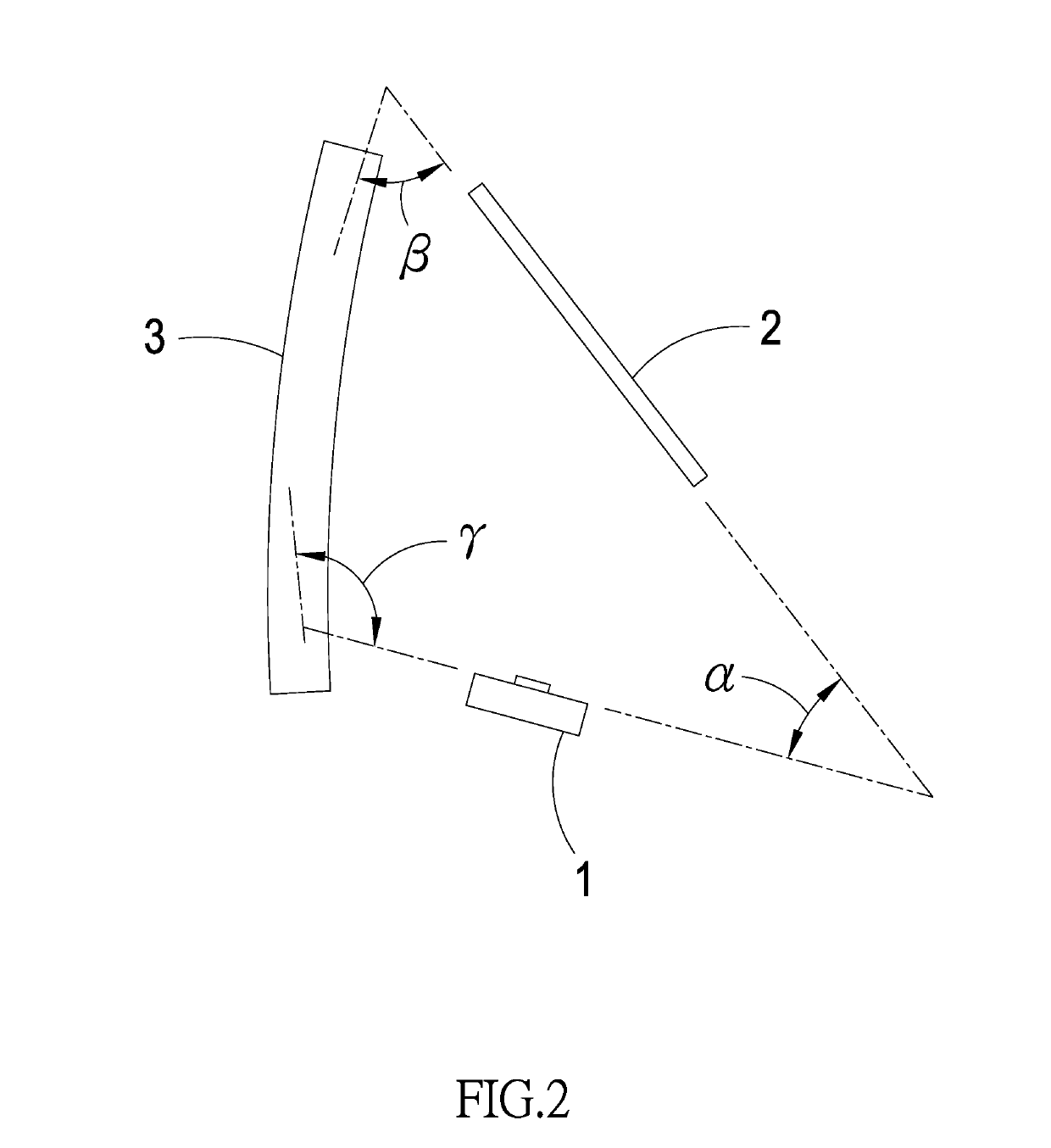
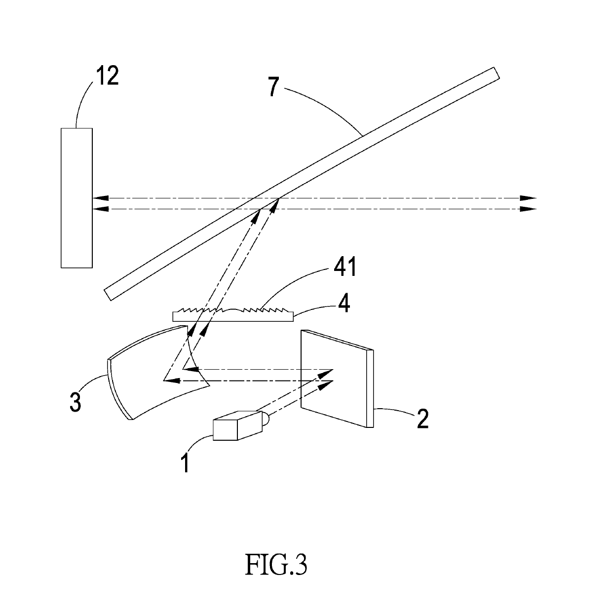
[0021]As shown in FIG. 2 and FIG. 3, the present invention includes: an imaging unit 1 to project at least one predefined image 12; a reflector 2 to receive and reflect the predefined image 12; a reflective curved mirror 3 set at one side of the imaging unit 1 and located in the reflective path of the reflector 2 to provide for adjusting the imaging path, reducing the virtual image aberration, and projecting the predefined image 12 on a windshield 7 and furthermore reflecting to the user's ...


PUM


Abstract

The structure of the present invention majorly includes: an outer shell body; at least one connection portion; and an optical projection system set inside the outer shell body. The optical projection system includes: an imaging unit; a reflector; a reflective curved mirror; and at least one optical lens; wherein the imaging unit projects the predefined image and incidents on the reflective curved mirror after being reflected by the reflector to adjust the imaging path and correct the aberration. And, the optical lens will magnify the predefined image in the imaging path to make the predefined image reflected to the user's eyes through the windshield to form the virtual image of the predefined image refracted outside the windshield. The present invention can realize the triangle imaging principle in a smaller space, enlarge the imaging range, reduce the aberration problem, and simply set outside the dashboard through the outer shell body.

Description

(a) TECHNICAL FIELD OF THE INVENTION[0001]The present invention relates to an optical projection system and the devices thereof, which combines a Head Up Display (HUD) having a simple structure, a smaller volume, the ability to virtually image at a long-distance, and a smaller image aberration into a detachable outer shell body to have the convenience for the after-assembly market.(b) DESCRIPTION OF THE PRIOR ART[0002]As shown in FIG. 1, which is the implementation schematic diagram of the conventional Head Up Display (HUD). The HUD includes a box body 91, a display device 92, and at least two optical mirrors 93, 94. The driver can watch the virtual image of the image information through the windshield 95.[0003]Wherein, the two-dimensional image is projected out by the box body 91 in a certain Field Of View (F.O.V), so the box body 91 is necessary to have a certain volume for projecting the image onto the windshield 95 through the optical mirrors 93, 94 and the box body 91 have to b...

Claims


Application Information

Patent Timeline
IPC IPC(8): G01C21/36G02B27/01B29D11/00
CPCG01C21/365G02B27/0101B29D11/00596G02B2027/0145G02B2027/011G02B2027/0112G02B2027/014G02B2027/0187G02B2027/015
Inventor CHEN, YING-YUN
Owner BUENOOPTICS CO LTD
Why Eureka
Try Eureka