Method and device for power adjustment in ue and base station

a technology of power adjustment and wireless communication system, applied in the direction of transmission path sub-channel allocation, power management, wireless communication, etc., can solve the problems of new problems to reset accumulation in the uplink power control mechanism, significant differences in long-term channel fading experience, and large so as to simplify the power control complexity and reduce the complexity of the uplink power control of the ue

Active Publication Date: 2019-10-17
SHANGHAI QIYU COMM TECH SERVICE CENT
View PDF3 Cites 4 Cited by
  • Summary
  • Abstract
  • Description
  • Claims
  • Application Information

AI Technical Summary

Benefits of technology

[0161]Compared with the prior art, the present disclosure has the following technical advantages:
[0162]The K power offset value(s) corresponds(correspond) to the K transmission power value Control (TPC) indication(s) after the first operation is triggered. An accumulation reset corresponding to the first power value is triggered by reception of the first information. The first information corresponds to the P antenna port group(s) rather than the first antenna port group corresponding to the first wireless signal. The accumulation reset of the first power value is triggered only when the P antenna port groups are reset. The frequent reset of the uplink transmitting power due to the change of the corresponding antenna port group is avoided, and the complexity of the uplink power control of the UE is reduced.
[0163]The large-scale fading corresponding to the P antenna port group(s) is similar. The uplink power control of the UE is operated by referring to the average pathloss value9 (Pathloss) of the wireless signals transmitted by the P antenna port group(s), thereby simplifying the power control complexity.

Problems solved by technology

This causes significant differences among long-term channel fading experienced by signals using different beamforming vectors.
This differences among long-term channel fading brings new problems to Reset of Accumulation in the uplink power control mechanism.
However, there is an obvious problem with this method.
When the UE is configured with multiple antenna port groups at the same time, and the switching between multiple antenna groups is frequent, the above-mentioned independent accumulation reset based on each antenna port group brings great complexity to the uplink power control, and results in a problem of frequent reset.
If the uplink transmitting power is determined only by the first antenna port group corresponding to the first wireless signal, the uplink transmitting power will vary greatly and is unstable, which is disadvantageous for receiving by the base station.

Method used


Image

  • Method and device for power adjustment in ue and base station
  • Method and device for power adjustment in ue and base station
  • Method and device for power adjustment in ue and base station

Examples


embodiment 1

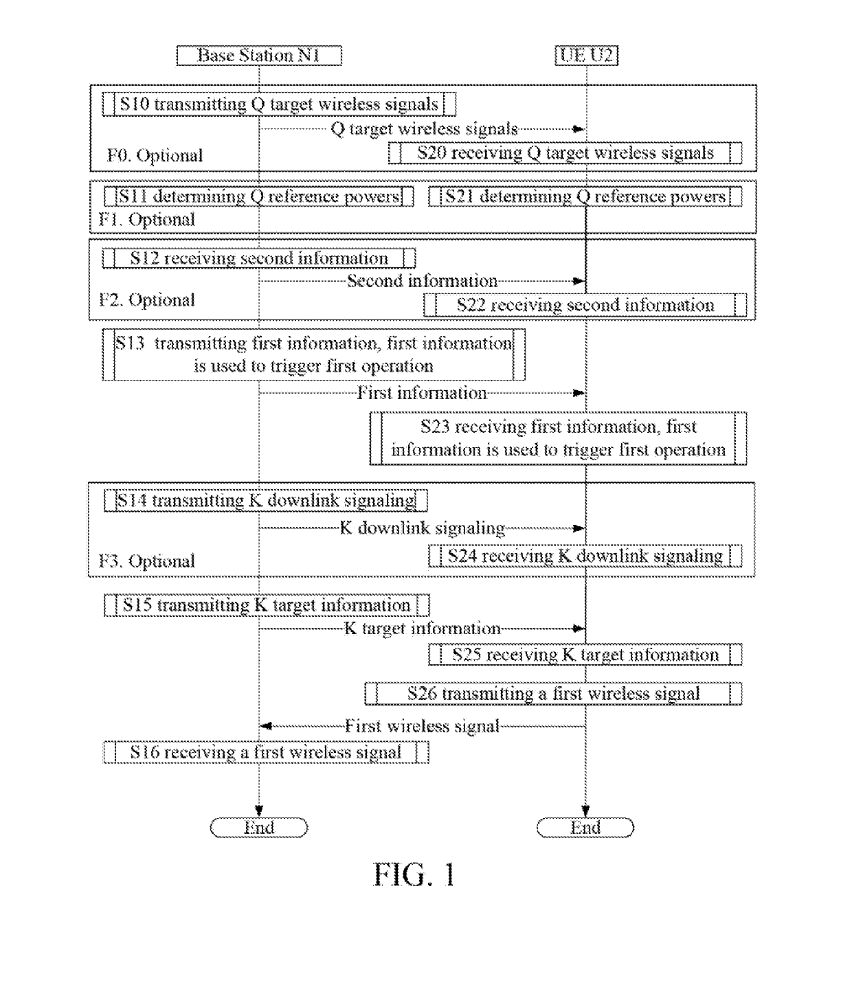
[0175]Embodiment 1 Illustrates a flow chart showing a first information transmission in accordance with an embodiment of the present disclosure, as shown in FIG. 1. In FIG. 1, the base station N1 is a maintenance base station for the serving cell of the UE U2. The steps identified by block F0, block F1, block F2 and block F3 are optional, respectively.

[0176]For the base station N1, Q target wireless signals are transmitted in step S10; Q reference powers are determined in step S11; the second information is transmitted in step S12; the first information is transmitted in step S13, and the first is used to trigger the first operation; K downlink signalings are transmitted in step S14; K piece(s) of target information is(are) transmitted in step S15; the first wireless signal is received in step S16.

[0177]For the UE U2, the Q target wireless signals are received in step S20; the Q reference powers are determined in step S21; the second information is received in step S22; the first in...

embodiment 2

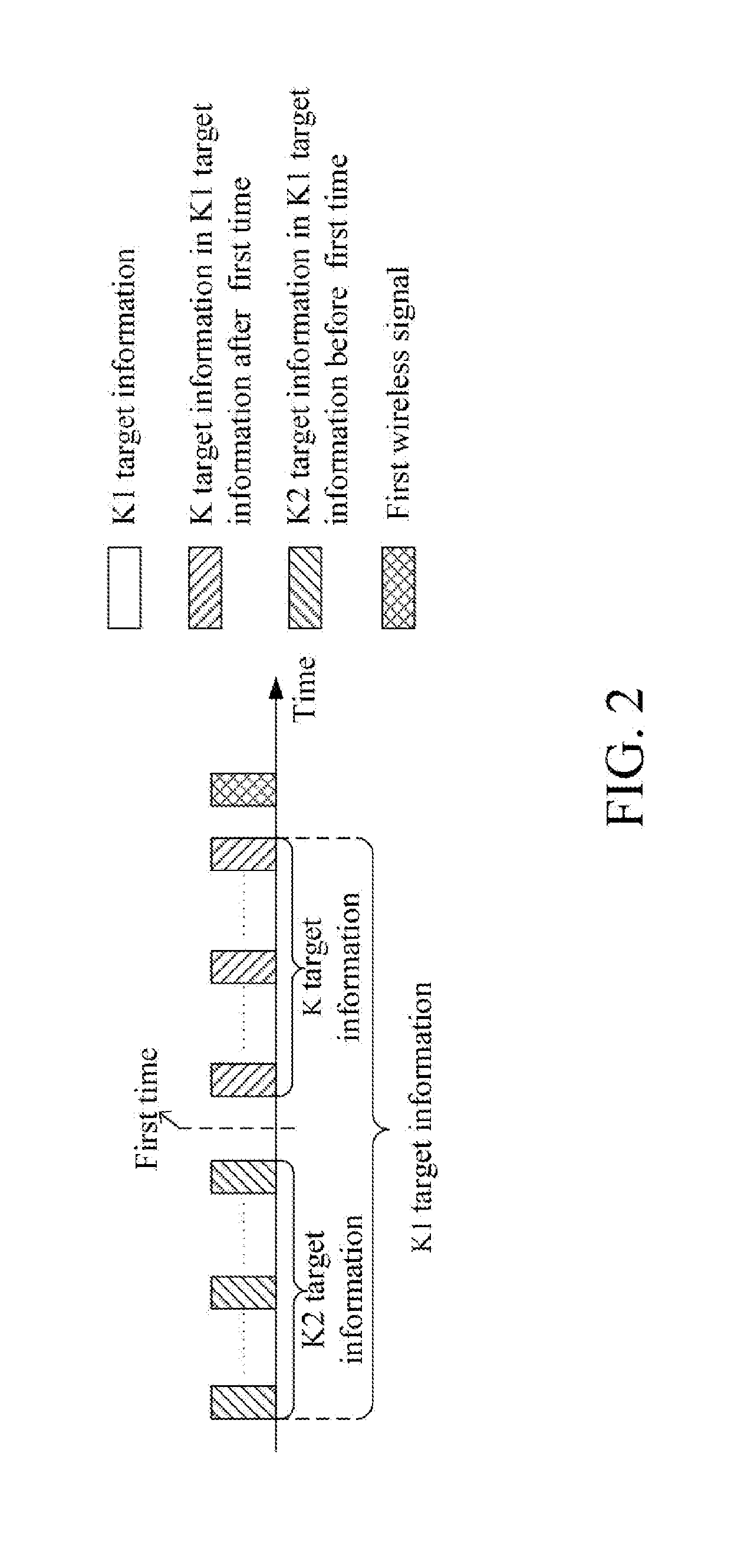
[0185]Embodiment 2 Illustrates a time domain diagram for triggering a first operation, as shown in FIG. 2. In FIG. 2, the square marked by the thick line frame is one of the target information of the K1 target information, the square filled with slashes is one of the K2 piece(s) of target information, and the square filled with backslashes is one of the K piece(s) of target information. The K1 pieces of target information is composed of the K2 piece(s) of target information and the K piece(s) of target information.

[0186]In Embodiment 2, in a given time window, the UE receives K1 pieces of target information in total, and the UE receives the first information at a first time. Among the K1 pieces of target information, K piece(s) of target information is(are) after the first time in the time domain. Among the K1 target information, K2 piece(s) of target information is before the first time in the time domain. The K1 is equal to the sum of the K and the K2. The first wireless signal of...

embodiment 3

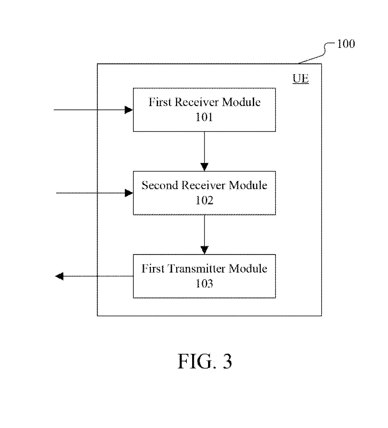
[0192]Embodiment 3 Illustrates a structural block diagram of a processing device in a UE, as shown in FIG. 3. In FIG. 3, a processing device 100 in the UE comprises a first receiver 101, a second receiver 102 and a first transmitter 103.

[0193]The first receiver 101 is configured to receive first information; the first information being used to trigger a first operation.

[0194]The second receiver 102 is configured to receive K piece(s) of target information.

[0195]The first transmitter 103 is configured to transmit a first wireless signal.

[0196]In Embodiment 3, a transmission power value of the first wireless signal is a first power value. The first power value is irrelevant to all piece(s) of target information received prior to triggering the first operation. The K piece(s) of target information is(are) received after triggering the first operation. The sum of K power offset value(s) is used to determine the first power value. The K power offset value(s) is(are) respectively indicate...


PUM


Abstract

A method and device for power adjustment in a user equipment and a base station are disclosed in the present disclosure. The user equipment receives first information which is used to trigger a first operation, and then receives K piece(s) of target information and transmits a first wireless signal. A transmission power value of the first wireless signal is a first power value; the first power value is irrelevant to all piece(s) of target information received prior to triggering the first operation. The K piece(s) of target information is(are) received after triggering the first operation. The sum of K power offset value(s) is used to determine the first power value. The K power offset value(s) are respectively indicated by the K piece(s) of target information.

Description

CROSS-REFERENCE TO RELATED APPLICATION[0001]This application is a continuation of International Application No. PCT / CN2017 / 114557, filed Dec. 5, 2017, claiming the priority benefit of Chinese Patent Application Serial Number 201611253311.4, filed on Dec. 29, 2016, the full disclosure of which is incorporated herein by reference.BACKGROUNDTechnical Field[0002]The present disclosure relates to a transmission method and device for supporting power adjustment in a wireless communication system, and more particularly to a transmission scheme and device for supporting power adjustment in a wireless communication system in which a large number of antennas are deployed on a base station side.Related Art[0003]In the existing Long Term Evolution (LTE) system, Reset of Accumulation in the uplink power control mechanism is triggered by the reconfiguration of the p0-UE-PUSCH field in the Radio Resource Control (RRC) signaling or Random Access Response (RAR) information. The p0-UE-PUSCH field is ...

Claims


Application Information

Patent Timeline
Patent Type & Authority Applications(United States)
IPC IPC(8): H04B7/0426H04L5/00H04W52/32H04W52/24
CPCH04L5/0023H04B7/043H04W52/325H04W52/242H04B7/0426H04L5/0053H04W52/146H04W52/243H04W52/246H04W72/121H04W72/23H04W52/42H04L5/0055H04L5/0048H04L27/34H04B7/0691
Inventor JIANG, QIZHANG, XIAOBO
Owner SHANGHAI QIYU COMM TECH SERVICE CENT
Why Eureka
Try Eureka